20
INTELLIGENT ACTUATOR
Part 1 Installation
(7) Motor connector
This connector is used to drive the motor inside the actuator.
Motor Connector Specifications
Item Description Details
Connector GIC2.5/4-STF-7.62
4-pin, 2-piece connector by
Phoenix Contact
Connector name M1 to 6 Motor connector
Cable size
0.75 mm
2
(equivalent to
AWG18)
Supplied with the actuator.
Connected unit Actuator
1
PE Protective grounding wire
2
Out U Motor drive phase U
3
Out V Motor drive phase V
Terminal
assignments
4
Out W Motor drive phase W
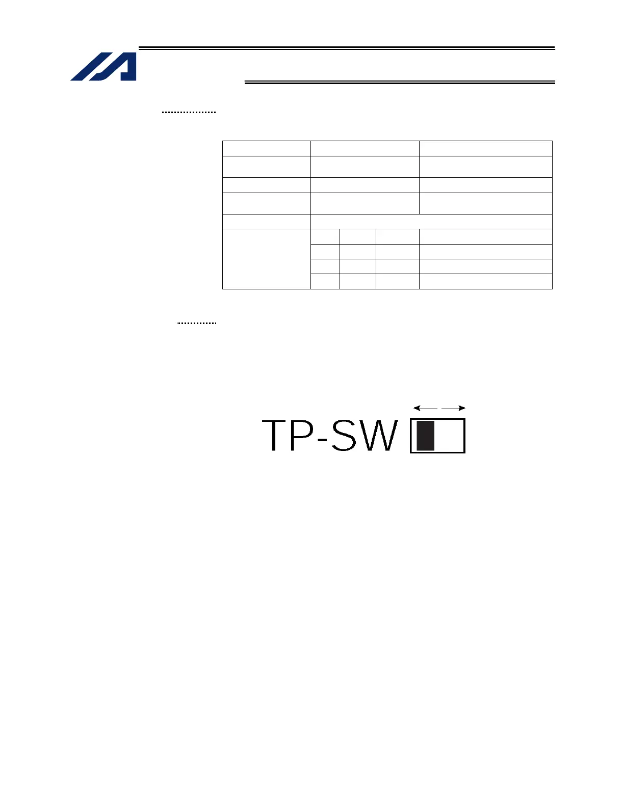
(8) Teaching-pendant type
switch (P type only)
This switch is used to change the type of the teaching pendant connected
to the teaching connector (9). It switches between “IAI’s standard teaching
pedant” and “ANSI teaching pendant.” The switch is located on the front
side of the board. Select the applicable setting in accordance with the
teaching pendant used.
Left: PC cable (comforming to safety category 4) Right: PC cable
SEL-T, SEL-TD, SEL-TG teaching pendant IA-T-X, IA-T-XD teaching
pendant
IA-T-XA teaching pendant
Note 1: The safety gate switch will not function if this switch is not set
correctly.
Note 2: Q type controllers connot be used with IAI’s standard teaching
pendants.
Note 3: The TP switch is not provided on Q type controllers.
Switch

 Loading...


