10-41
PHYSICAL DESIGN AND SYSTEM DEBUGGING
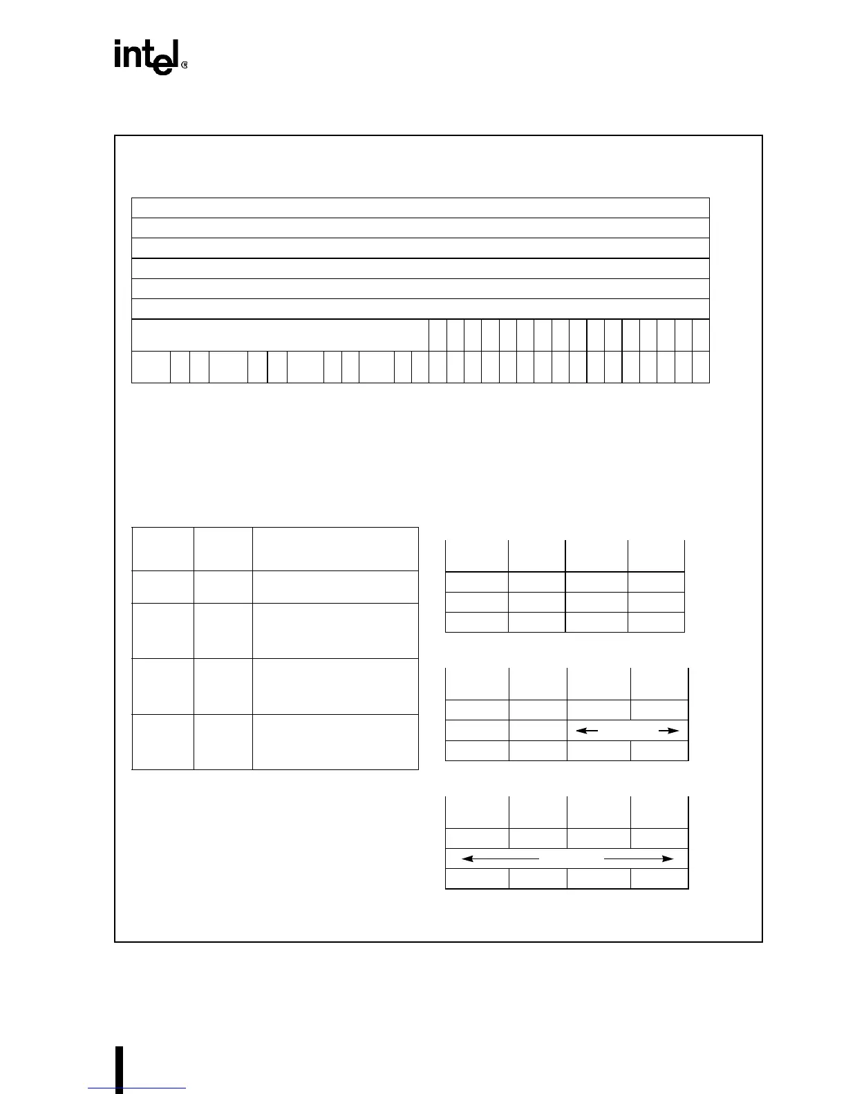
Figure 10-31. Debug Registers
31 16 15 0
Breakpoint 0 Linear Address DR0
Breakpoint 1 Linear Address DR1
Breakpoint 2 Linear Address DR2
Breakpoint 3 Linear Address DR3
Intel Reserved. Do not define. DR4
Intel Reserved. Do not define. DR5
0B
T
B
S
B
D
000000000
B
3
B
2
B
1
B
0
DR6
LEN
3
R
3
W
3
LEN
2
R
2
W
2
LEN
1
R
1
W
1
LEN0
R
0
W
0
00
G
D
000
G
E
L
E
G
3
L
3
G
2
L
2
G
1
L
1
G
0
L
0
DR7
31 16 15 0
Note: 0 indicates Intel reserved: Do not define.
LENi
Encoding
Breakpoint
Field Width
Usage of Least Significant Bits in
Breakpoint Address
Register i, (i = 0–3)
00 1 Byte All 32 bits used to specify a single-
byte breakpoint field.
01 2 Byte A31–A1 used to specify a two-byte
word-aligned breakpoint field. A0 in
breakpoint address register is not
used.
10 Undefined
–Do not
use this
encoding.
11 4 Byte A31–A2 used to specify a four-byte
dword-aligned breakpoint field. A0
and A1 in breakpoint address
register are not used.
DR2 = 00000005H; LEN2 = 00B
DR2 = 00000005H; LEN2 = 01B
DR2 = 00000005H; LEN2 = 11B
31 0
00000008H
BKPT FLD2 00000004H
00000000H
31 0
00000008H
00000004H
00000000H
31 0
00000008H
00000004H
00000000H
BKPT FLD2
BKPT FLD2