USER MANUAL
INTEL® FALCON™ 8+ UAS
© 2018 Intel Corporation. All rights reserved 208
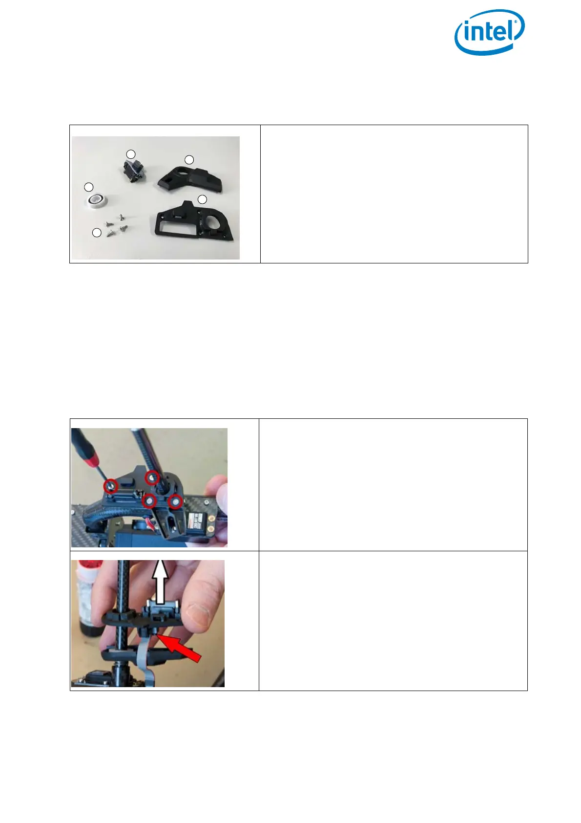
The payload adapter consists of the following parts:
The following figures show step by step instructions how to exchange a payload
adapter.
In the single images
• red arrows and red circles are used to emphasize a specific region or detail of a
part or assembly;
• white arrows are used to indicate a movement (straight arrow) or a rotation
(bend arrow) of a part or assembly.
Figure 6.6: The parts of the payload adapter
(1) Ball bearing
The ball bearing might look different than
depicted. There are versions made from
plastic or metal.
(2) Circuit board
(3) Back plate
(4) Front plate
(5) Four screws C2.2x6.5 mm TX, SK
Figure 6.7: Removing a payload adapter from a payload
1. Remove the 4 screws C2.2x6.5 mm TX, SK.
Use a T6 torx screw driver.
Make sure not to apply force to the servo
motor.
2. Disconnect the front plate and the back plate
of the payload adapter.
3. Disconnect the 10 pin wire connector.