Hardware Installations and Upgrades
Intel® Entry Server Chassis SC5299-E DP/WS/BRP User Guide 53
13. Route the P1, P2, and P14 power cables to the server board and connect to appropriate
connectors. Refer to the Intel
®
Server Board Quick Start User’s Guide or User Guide
that came with your Intel
®
server board for the location of power connections.
14. Route the P8, P9, P10, and P12 cables to the hard drive cage and connect power
cables to any installed devices.
15. Route the P3 and P4 cables to the 5.25-in. removable media device bays and connect
to any installed devices.
16. Route the P5 cable to the floppy drive, if installed.
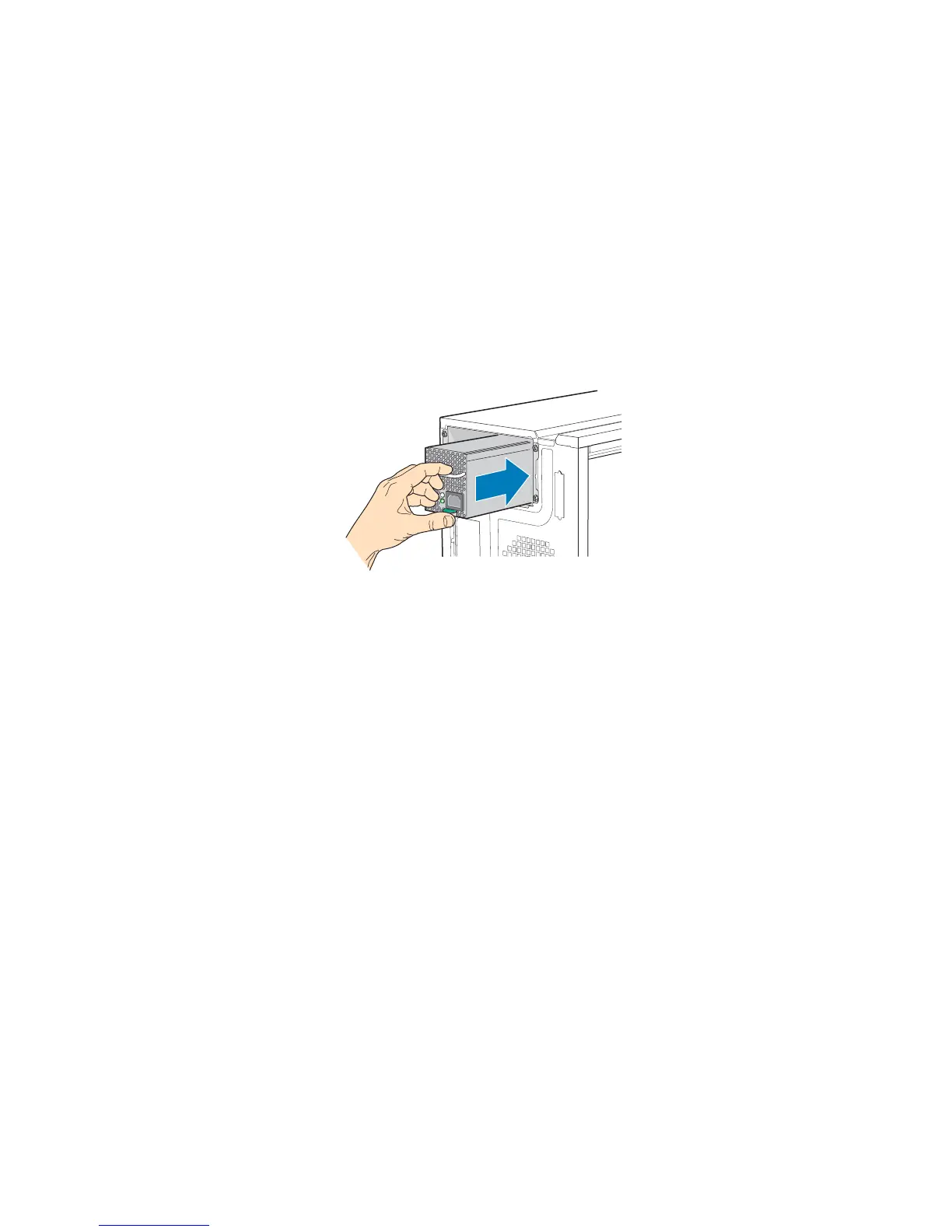
17. Reinstall the hot swap power supply module(s). The power supply module(s) will
click into place when properly seated.
Figure 69. Re-installing Hot Swap Power Supply Module(s)
18. Install the left side cover. For instructions, see “Installing the Left Side Cover”.
19. Reconnect all peripheral devices and the AC power cable(s) to the server. Power up
the server.
TP01768