EasyManuals Logo

Interroll MultiControl User Manual

Interroll MultiControl
131 pages
To Next Page IconTo Next Page
To Previous Page IconTo Previous Page
Page #126 background imageLoading...
Page #126 background image
Interface Box for VDC Motors
Operating and Programming 121
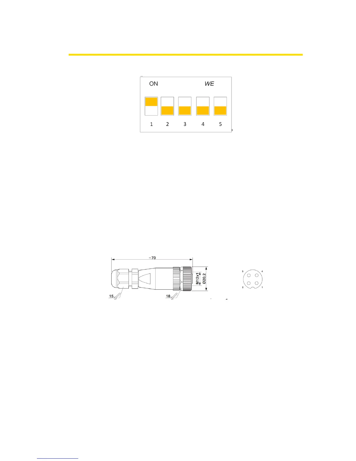
DIP switch of the Interface Box
With different settings of the DIP switch on the interface box, different parameters are transferred
to the motors, see table.
1
2
3
4
5
HPD
L
L
L
L
L
Transfer 28 A
H
L
L
L
L
Transfer 20 A
H
H
L
L
L
Transfer 12 A
L
L
H
L
L
Reclaim Unit 28 A
L
H
L
L
L
This plug is included with delivery.
Cable outer diameter: 4-6mm
Pins 1 and 2 must both be connected with + 24V.
Pins 3 and 4 must be connected to 0V.
Power RollerDrive of MultiControl is connected to the interface box as standard.
Power Logic can be optionally connected by the customer.

Table of Contents

Other manuals for Interroll MultiControl

Questions and Answers:

Question and Answer IconNeed help?

Do you have a question about the Interroll MultiControl and is the answer not in the manual?

Interroll MultiControl Specifications

General IconGeneral
Power Supply24 VDC
Rated Voltage24 VDC
Storage Temperature-20 °C to +70 °C
Communication ProtocolsEthernet/IP, PROFINET, EtherCAT, CANOpen
Number of Channels4
Weight0.5 kg

Related product manuals