iPECS UCP
Hardware Description and Installation Manual Issue 1.3
92
AC/DC Adapter
Before wiring any of the Modules, first connect the “ ” screw on the back of the Module to a
known ground, refer to 6.1.4.
On the front of the SLTM32 is the RJ–45 type “LAN” connector. This connector should be wired
to the appropriate LAN points as discussed in 6.1.6 and 6.1.7.
Wire “LAN” to a 10/100 Base-T switch, an ES8G/ES8GP can be used to connect to the
LAN.
Tag or number wiring for maintenance.
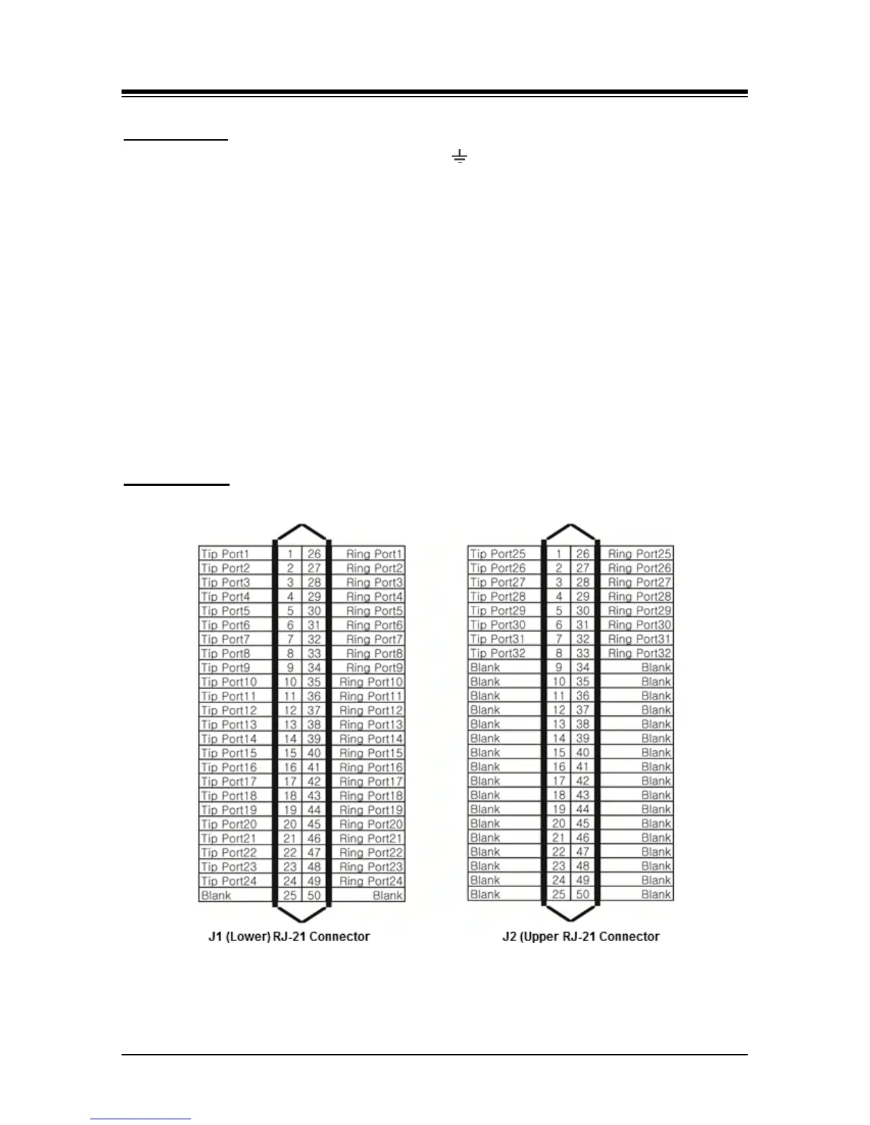
On the rear are two (2) 25-pair RJ-21x style connectors terminated as shown in Figure 6.11-2.
These connectors should be wired to the SLT termination point as shown in the figure.
Wire each RJ-21x to an SLT device/MDF.
Tag or number wiring for maintenance.
AC Power Cord
Assure the AC power cord is plugged into the power input of the SLTM32 and a live AC outlet.
Figure 6.11-2 SLTM32 RJ-21X Connector Configuration