iPECS UCP
Hardware Description and Installation Manual Issue 1.3
112
7.3 SLT Installation
7.3.1 SLT Wiring
SLTs are wired to the center pair of the RJ11 jack, typically on the bottom or back of the SLT. The
wall outlet should be connected to an appropriate SLT port in the iPECS UCP system.
1. Wire the center pair of the wall outlet to the termination point using UTP cable.
2. Using the line cord provided with the SLT, connect the SLT to the wall outlet.
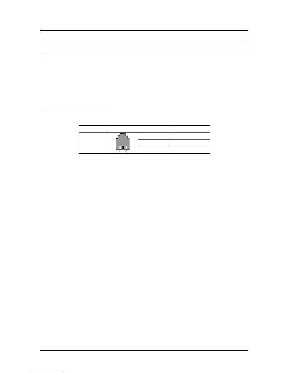
Modular Jack Pin Assignment
Table 7.3.1-1 SLT Modular Jack Wiring
 Loading...


