iPECS UCP
Hardware Description and Installation Manual Issue 1.3
100
6.17 Main Cabinet Wiring
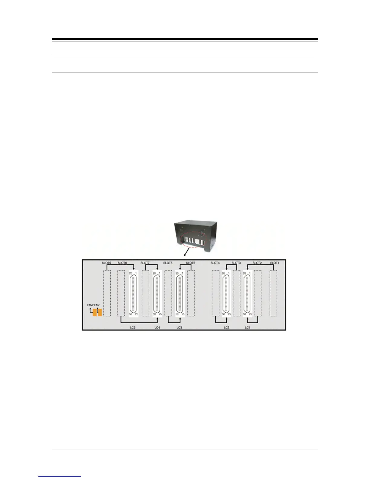
With the Enhanced Main Cabinet, telephony connections (PSTN, ISDN, SLT, and DTIM) are
through male RJ-21X 25-pair connectors mounted on the back panel. Modules terminate the
telephony interfaces at the appropriate connector on the back plane. The relationship between
slots and RJ-21X connectors is shown in Figure 6.17-1.
Note the, WTIM4 and WTIM8 terminate directly to the DECT Base Stations and do not terminate
in the male RJ-21X connectors of the Main Cabinet.
Complete all the telephony wiring for the Module prior to installing and applying power to the
Module. Note also consider the slot and sequence assignments when installing Modules, refer to
6.1.1.
Complete all telephony wiring by making cross-connects between the RJ-21X and the
appropriate telephone company termination point. For details, see Table 6.17-1. For the PRIM
only Port 1 is connected, and for the BRIM2 and BRIU2 only Port 1 and Port 2 are connected.
Figure 6.17-1 RJ-21x Connector Backplane Wiring Diagram