iPECS UCP
Hardware Description and Installation Manual Issue 1.3
34
3.1.13 WTIM (Wireless Telephone Interface Module)
3.1.13.1 WTIM4
The WTIM4 (Wireless Terminal Interface gateway Module) provides connections for four (4)
Ericsson-LG Enterprise multi-channel DECT Base stations. The DECT Base station acts as the
Remote Fixed Part (RFP) defined in the DECT specifications. The GDC-400B, GDC-600B and
GDC600BE DECT Base Stations are supported.
DECT handsets can be used if the Base station is connected to a WTIM4 and the proper
Attendant programming is completed. The WTIM4 contains a processor for IP to TDM voice and
signaling conversion and DSP circuitry to provide transcoding for each channel. The Base station
can be connected to the WTIM4 up to 600 meters from the gateway using 24 AWG twisted pair
cabling.
The WTIM4 includes a 10/100 Base-T Ethernet interface as well as packet voice processing
functions. The Ethernet port incorporates auto MDI, MDIX switching, therefore, both straight and
cross cables can be used.
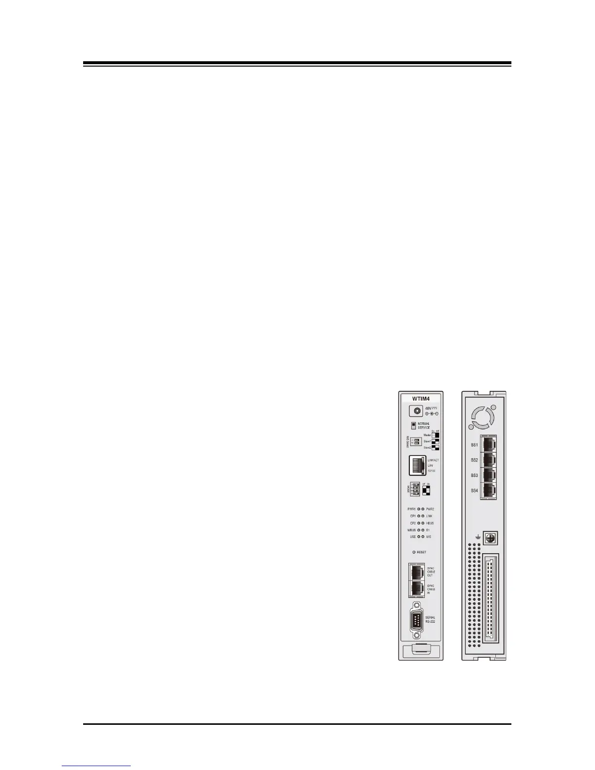
As shown in Figure 3.1.13.1-1, the front panel of the WTIM4 has:
Power jack for the AC/DC adapter; see 3.1.15 AD/DC adapter –G-
Two (2) green power status LEDs
PWR1 - + 3.3 VDC
PWR2 - + 30 VDC
Normal/Service switch – In Service mode, circuits in use are
busied as they return to idle
RJ-45 Female LAN connector with Speed and Link/Activity
LEDs
Four position Mode switch
Eight (8) WTIM4 status LEDs
Two RJ-45 Sync connectors to link WTIMs
2-position control switch
DB-9 RS-232 connector
Reset Switch
On the rear panel, the WTIM4 has:
Four (4) RJ-45 female connectors
Ground Lug
Fifty (50)-pin back plane connector
Figure 3.1.13.1-1 WTIM4 Front & Rear Panels