iPECS UCP
Hardware Description and Installation Manual Issue 1.3
80
6.4 VCIM Installation
The VCIM may be installed anywhere except for slot 10 of the cabinet, or may be installed
anywhere in the Desk Mount Holder. The VCIM is used to provide packet relay for remote
devices to communicate with the host and translation between the iPECS proprietary protocols
and other standard protocols (H323, SIP) or multi-party voice conferences.
LEDs
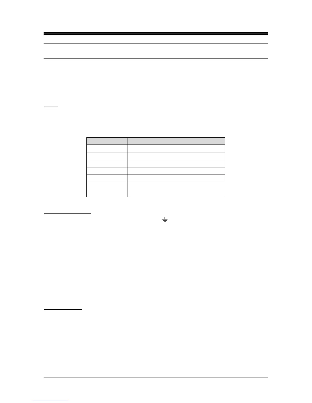
The VCIM have six (6) LEDs for status and diagnostic information as in Table 6.4-1.
Table 6.4-1 VCIM Status LED Functions
Registered to UCPs
S5
Transcoding in use
S6
MCIM Task Flashing
(ON – Conf. channel in use, Flashing – Idle)
Wiring Connectors
Before wiring any of the Modules, first connect the “ ” screw on the back of the Module to a
known ground, refer to 6.1.4. If installed in a cabinet assure the cabinet is grounded.
A “LAN” RJ45 type connector is located on the front of the VCIM. This connector should be wired
to the appropriate LAN points as discussed in 6.1.6 and 6.1.7. In addition, the VCIM includes an
unused “LAN” RJ-45 type connector. Currently this LAN port is not used and no connection
should be made to this port.
Wire “LAN” to a 10/100/1000 Base-T switch, an ES8G/ES8GP can be used to connect to
the LAN. (LAN1 – 10/100/1000 Base-T, LAN2 – 1000 Base-T only)
Tag or number wiring for maintenance.
AC/DC Adapter
If a PSU is not employed, assure the AC/DC Adapter is plugged into a live AC outlet and the
Module Power jack.