iPECS UCP
Hardware Description and Installation Manual Issue 1.3
36
3.1.14 PSU (Power Supply Unit)
The Power Supply Unit (PSU) converts 100-240 VAC @ 50/60 Hz to -48V and 5V DC. The DC
voltages are connected to the back plane for distribution to modules installed in the Enhanced
Main Cabinet. Power is connected via the back plane connector on the PSU and individual
modules.
In most configurations, the PSU is capable of supplying 48 VDC power to a full cabinet of nine (9)
modules. The current draw for the different modules varies greatly; PSTN, ISDN other modules
require about 5 watts each while an ES8GP powering eight (8) phones may require over 50 watts.
Designing a PSU to deliver power to nine ES8GP modules would create a cost penalty for most
configurations. A simple rule of thumb is to limit the number of DTIM4, DTIM8, WTIM4, WTIM8
and ES8G/ES8GP modules to five (5) per cabinet. To calculate the precise current draw of any
cabinet configuration, use the Power draw chart in Table 2.4.4.2-1. The total current required
must be less than the PSU capacity, 5.3 amps. If more than the PSU capacity, reconfigure the
cabinet modules or install some of the modules in a second cabinet with a separate PSU.
The PSU includes a DB9 connector for RS-232 communication with gateway modules for alarm
notifications.
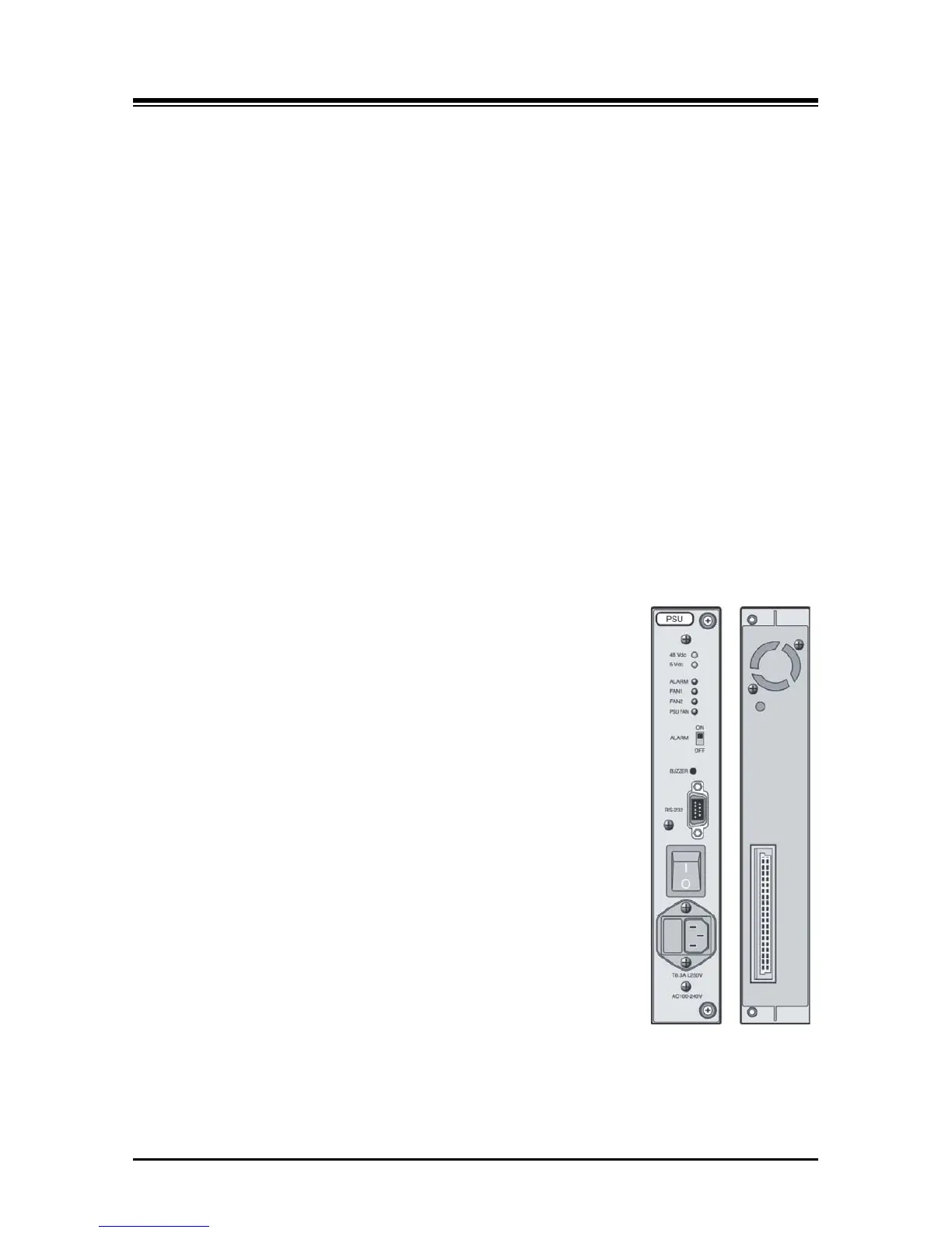
As shown in Figure 3.1.14-1, the front panel of the PSU has:
Six (6) Status LEDs
Alarm Switch – to activate local audio alarm via the buzzer
Buzzer for local audio indication of alarm condition
DB-9 RS-232 connector
Power Switch
AC Power Input
Fuse
On the rear panel, the PSU has:
Thirty-two (32)-pin back plane connector
Figure 3.1.14-1 PSU Front & Rear Panels