iPECS UCP
Hardware Description and Installation Manual Issue 1.3
93
6.12 UVM Installation
The UVM may be installed anywhere except for slot 10 of the cabinet, or may be installed
anywhere in the Desk Mount Holder. The UVM module provides voice storage and processing for
Automated Attendant and Voice Mail capabilities as well as other Voice Processing features.
The UVM module supports eight (8) channels with 50 hours of storage and expands to 16
channels with up to 200 hours of storage by installing appropriate licenses.
LEDs
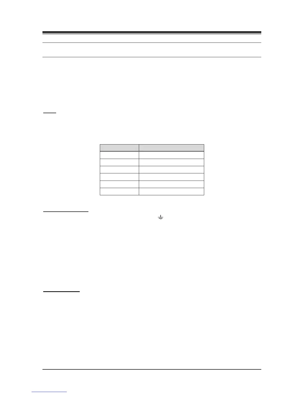
In addition to the Power and LAN LEDs, the UVM has six (6) LEDs for status and diagnostics
information as shown in Table 6.12-1.
Table 6.12-1 UVM Status LED Functions
Wiring Connectors
Before wiring any of the Modules, first connect the “ ” screw on the back of the Module to a
known ground, refer to 6.1.4. If installed in a cabinet assure the cabinet is grounded.
On the front of the UVM is the RJ 45 type “LAN” connector. This connector should be wired to the
appropriate LAN points as discussed in 6.1.6 and 6.1.7.
Wire “LAN” to a 10/100/1000 Base-T switch, an ES8G/ES8GP can be used to connect to
the LAN.
Tag or number wiring for maintenance.
AC/DC Adapter
If a PSU is not employed, assure the AC/DC Adapter is plugged into a live AC outlet and the
Module Power jack.