iPECS UCP
Hardware Description and Installation Manual Issue 1.3
94
6.13 MCIM Installation
The MCIM may be installed anywhere except for slot 10 of the cabinet, or may be installed
anywhere in the Desk Mount Holder. The MCIM performs the various conference functions for
multi-party voice conferences. With the MCIM, iPECS terminals can establish voice conferences
with up to 32 parties using the g.711 or g.729 codec or 24 parties with the g.723 codec.
LEDs
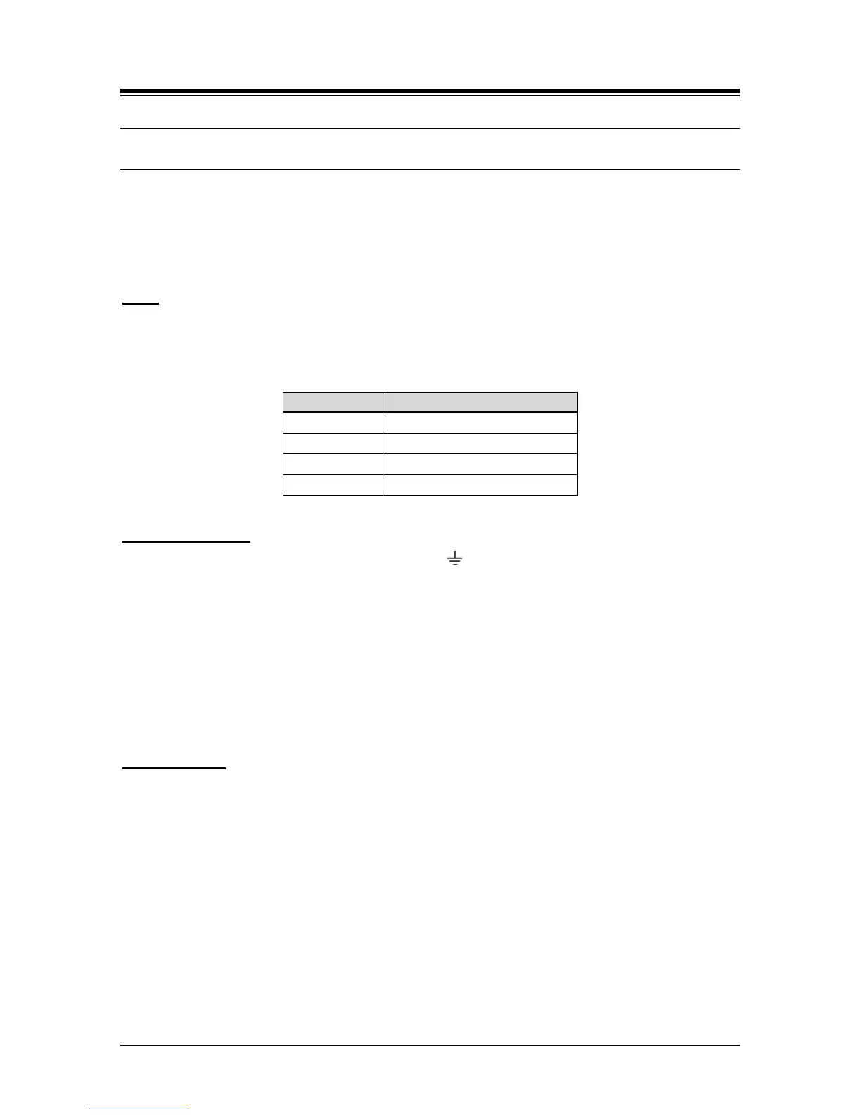
In addition to the Power and LAN LEDs, the MCIM has four (4) LEDs for status information as
shown in Table 6.13-1.
Table 6.13-1 MCIM Status LED Functions
Wiring Connectors
Before wiring any of the Modules, first connect the “ ” screw on the back of the Module to a
known ground, refer to 6.1.4. If installed in a cabinet assure the cabinet is grounded.
On the front of the MCIM is the RJ 45 type “LAN” connector. This connector should be wired to
the appropriate LAN points as discussed in 6.1.6 and 6.1.7.
Wire “LAN” to a 10/100 Base-T switch, an ES8G/ES8GP can be used to connect to the
LAN.
Tag or number wiring for maintenance.
AC/DC Adapter
If a PSU is not employed, assure the AC/DC Adapter is plugged into a live AC outlet and the
Module Power jack.