iPECS UCP
Hardware Description and Installation Manual Issue 1.3
66
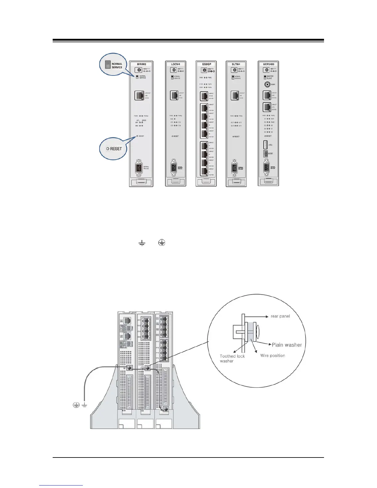
Figure 6.1.3-1 Common Module Switches
6.1.4 Module Grounding
As shown in Figure 6.1.4-1, a “ ” or “ ” screw is located on the rear panel of each Module. For
proper operation and code compliance, the grounding screw MUST be connected to a known
protective earth ground using a #12 AWG or larger UL-1015 type copper wire. The wire should be
located between the toothed lock washer and the plain washer. Note that when using the cabinet,
a separate ground connection to the individual Modules is not required.
Figure 6.1.4-1 Module Grounding