iPECS UCP
Hardware Description and Installation Manual Issue 1.3
67
CAUTION
When a module is installed in a Desk Mount Holder (DHLD) Wall Mount Holder (WHLD) or 1U-
Rack Mount Bracket (1U-RMB), the protective earth ground must be connected to the earth
ground terminal in rear of the module using #12 AWG or larger UL-1015 type copper wire.
6.1.5 Telephony Connections
In general, PSTN and SLT (telephony) connections are available on the rear of each Module,
while LAN, power and RS-232 connections are on the front of each Module. Except where noted,
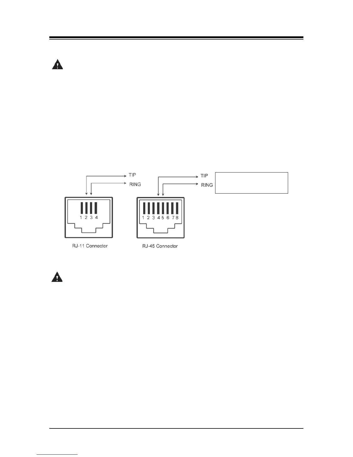
telephony connections via RJ-11 or RJ-45 type jacks are wired as in Figure 6.1.5-1. All telephone
wiring should use standard twisted pair 24 or 26 AWG wiring.
Figure 6.1.5-1 Telephony (RJ-11 or RJ-45) Connector Pin Assignment
CAUTION
To reduce the risk of fire, use only 26 AWG or larger UL List or CSA Certified Telecommunication
Line Cord.
6.1.6 LAN Connections
LAN connections are made by way of RJ-45 connectors on the front panel of each Module.
These connectors are shown in Figure 6.1.6-1 and Figure 6.1.6-2. Each connector has a green
Link/Activity LED and a yellow LAN speed LED, ON for 1000 Base-T.
The ES8GP can provide power over the LAN with 48 VDC across pin pairs 1 & 2 (+) and 3 & 6 (-).
This configuration mates with the LIP Phone as shown in the figure.
All LAN wiring (except UCPs, UVM, and Gigabit Switch) may use Category 5 Unshielded Twisted
Pair (CAT 5 UTP) cable. No single run of LAN cable should exceed 100 meters (about 330 feet).