iPECS UCP
Hardware Description and Installation Manual Issue 1.3
85
6.7 PRIM Installation
The PRIM Module may be installed anywhere except for slot 10 of the cabinet, or may be
installed anywhere in the Desk Mount Holder. The PRIM module provides a gateway for PRI line
connections to other iPECS appliances.
The PRIM module can support up to 30 PCM bearer channels for European ISDN Primary Rate
Interfaces or 23 PCM bearer channels for the North American Primary Rate Interface.
LEDs
In addition to the Power and LAN LEDs, the PRIM has four (4) LEDs for status and diagnostic
information as in Table 6.7-1.
CLK SLAVE PRIM module clock is synchronized with PRI Line
RUN Flashing when running
Wiring Connectors
Before wiring any of the Modules, first connect the “ ” screw on the back of the Module to a
known ground, refer to 6.1.4. If installed in a cabinet assure the cabinet is grounded.
On the front of the PRIM is the RJ 45 type “LAN” connector. This connector should be wired to
the appropriate LAN points as discussed in 6.1.6 and 6.1.7.
Wire “LAN” to a 10/100 Base-T switch, an ES8G/ES8GP can be used to connect to the
LAN.
Tag or number wiring for maintenance.
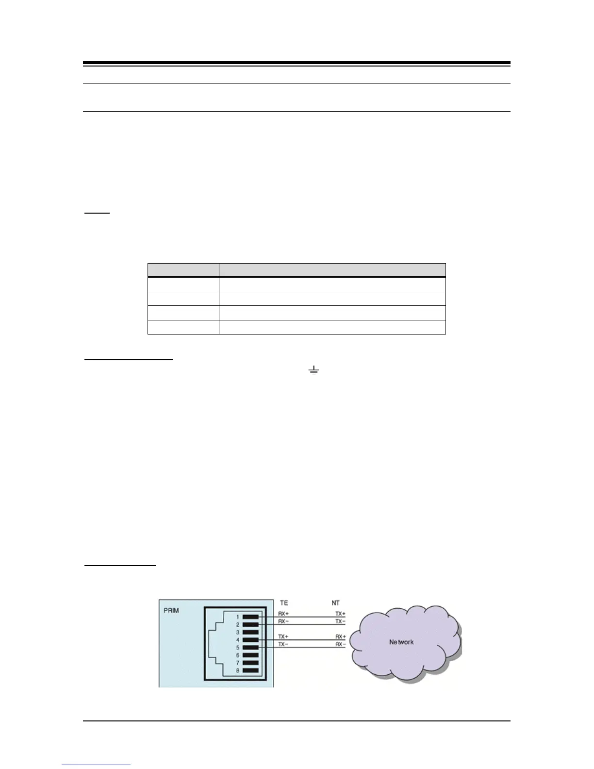
On the rear panel is a RJ-45 connector terminated to the PRI Line interface circuits. This
connector, refer to Figure 6.7-1, should be wired to the telephone company termination point.
Wire each RJ-45 to a PRI line at the ISDN termination point.
Tag or number wiring for maintenance.
AC/DC Adapter
If a PSU is not employed, assure the AC/DC Adapter is plugged into a live AC outlet and the
Module Power jack.
Figure 6.7-1 PRI Line Connector Configuration