iPECS UCP
Hardware Description and Installation Manual Issue 1.3
91
6.11 SLTM32 Installation
The SLTM32 is intended for installation in a 19” rack, it is NOT intended for installation in the
cabinet. The SLTM32 provides a gateway between thirty-two (32) standard Single Line
Telephone devices and other iPECS appliances.
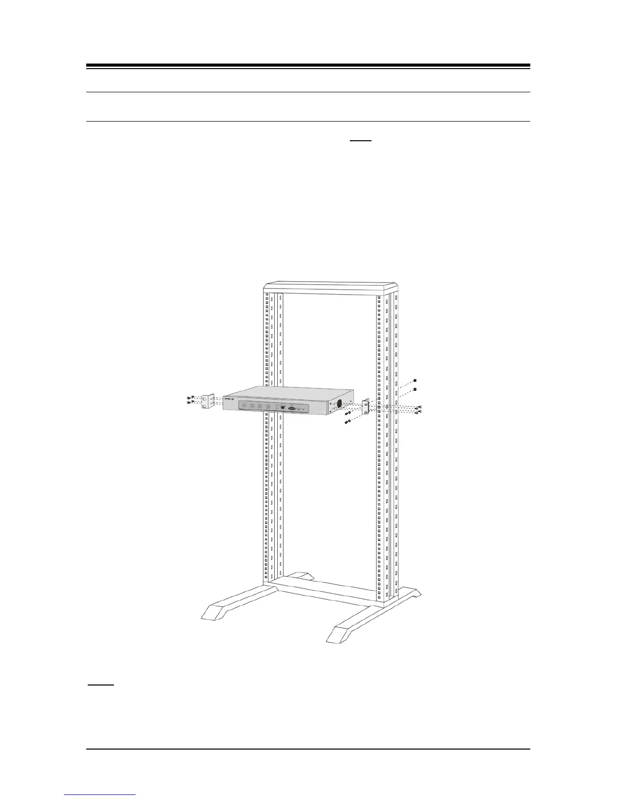
To mount the SLTM32 in a 19” rack,
1. Mount the left and right mounting brackets to the SLTM32 module using the eight (8)
machine screws provided as shown in Figure 6.11-1.
2. Mount the Module in the 19” rack with the four (4) machine screws, nuts and washers as
shown in Figure 6.11-1.
3. Complete the installation using the instructions for wiring given below.
Figure 6.11-1 SLTM32 Rack Mounting Installation
LEDs
In addition to the Power and LAN LEDs, the SLTM32 has Sixteen (16) dual color LEDs, which
indicate the status of the associated SLT port: in-use (LED ON), ringing (LED flashing) or idle
(LED OFF).