iPECS UCP
Hardware Description and Installation Manual Issue 1.3
26
3.1.7.2 DTIM24
The DTIM24 (Digital Terminal Interface gateway Module) supports 24 digital keysets (LKD and
LDP models). Keysets have access to all the resources of the iPECS as well as keyset
functionality and simple one-button feature access. The DTIM24 contains a processor for IP to
TDM and signaling conversion as well as DSP circuitry to provide transcoding for each channel.
Digital keysets can be connected up to 300 meters from the DTIM24 gateway using 24 AWG
twisted pair cabling.
The DTIM24 includes a 10/100 Base-T Ethernet interface as well as packet voice processing
functions. The Ethernet port incorporates auto MDI, MDIX switching, therefore, both straight and
cross cables can be used.
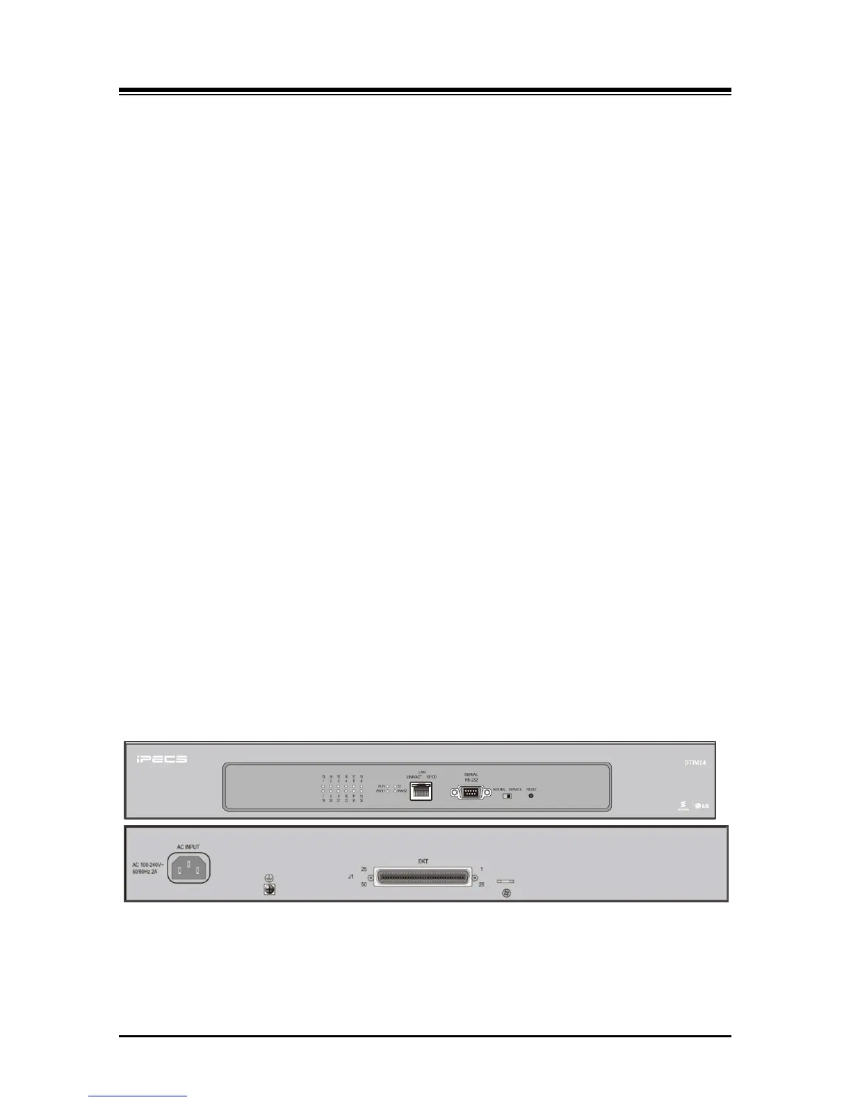
As shown in Figure 3.1.7.2-1 below, the front panel of the DTIM24 has:
Twelve (12) LEDs, one for status of each DKT
Run & Power status LED
PWR1 - + 5 VDC
PWR2 - + 30 VDC
RJ-45 Female LAN connector with Speed and Link/Activity LEDs
DB-9 RS-232 connector
Normal/Service switch – In Service mode, circuits in use are busied as they return to idle
Reset Switch
On the rear panel, the DTIM24 has:
AC input connector
Ground Lug
One (1) 25-pair RJ-21x connectors
Figure 3.1.7.2-1 DTIM24 Front & Rear Panels