iPECS UCP
Hardware Description and Installation Manual Issue 1.3
62
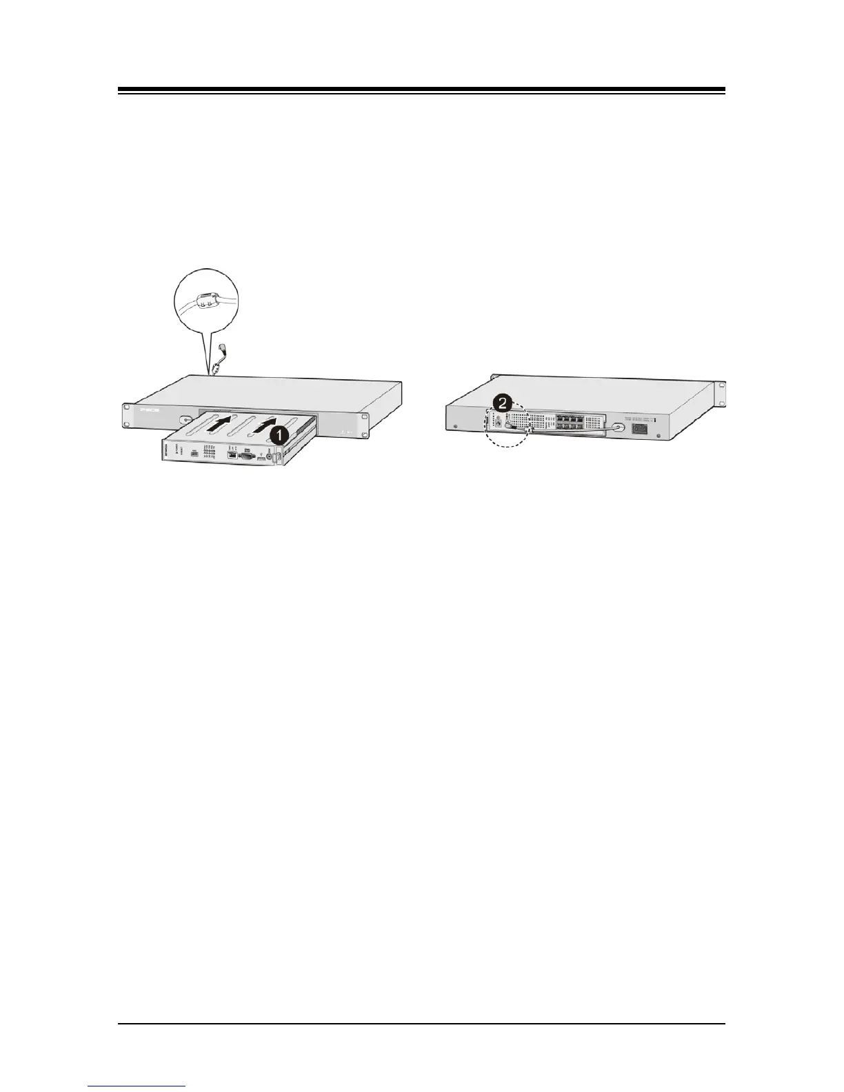
2. Install the gateway Module into the 1U-RMB and connect the adapter plug. Refer to
Figure 5.6-2.
a) Slide the Module into the 1U-RMB.
b) Place the Ferrite core over the DC cable and close the core over the cable. For the
RSGM, the DC cable must exit the rear of the 1U-RMB. For all other modules, the
DC cable must exit the front of the 1U-RMB.
c) Connect the adapter DC plug to the gateway Module.
Figure 5.6-2 1U-RMB Gateway Installation
3. Install the 1U-RMB in a standard 19” rack securely with four (4) appropriate machine
screws, nuts and lock-washers. Refer to Figure 5.6-3.
4. Wire the Module as described in section 6.
5.
Connect the AC cable to the adapter and wall outlet to power the Module.