iPECS UCP
Hardware Description and Installation Manual Issue 1.3
75
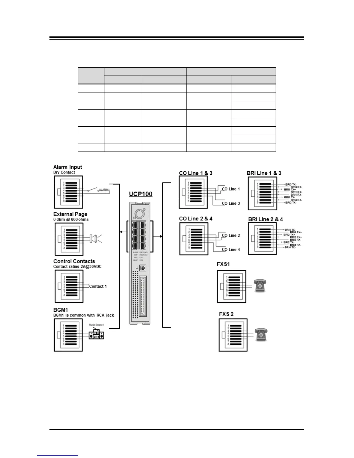
Table 6.2-3 Optional COIU4 & BRIU2/4 RJ-45 Pin assignment
RJ-45
1
N.C. N.C. BRI3_TX+ BRI4_TX+
2
N.C. N.C. BRI3_RX+ BRI4_RX+
3
CO3_R CO4_R BRI1_TX+ BRI2_TX+
4
CO1_R CO2_R BRI1_RX+ BRI2_RX+
5
CO1_T CO2_T BRI1_RX- BRI2_RX-
CO3_T CO4_T BRI1_TX- BRI2_TX-
7
N.C. N.C. BRI3_RX- BRI4_RX-
N.C. N.C. BRI3_TX- BRI4_TX-
Figure 6.2-1 UCP100 Miscellaneous & Telephony Connections
For the iPECS UCP600 and UCP2400 modules, the eight (8) RJ-45 connectors on the rear panel
are terminated for miscellaneous functions and Power Fail functions. Wire these connectors as
depicted in the sketch of Figure 6.2-2.