iPECS UCP
Hardware Description and Installation Manual Issue 1.3
82
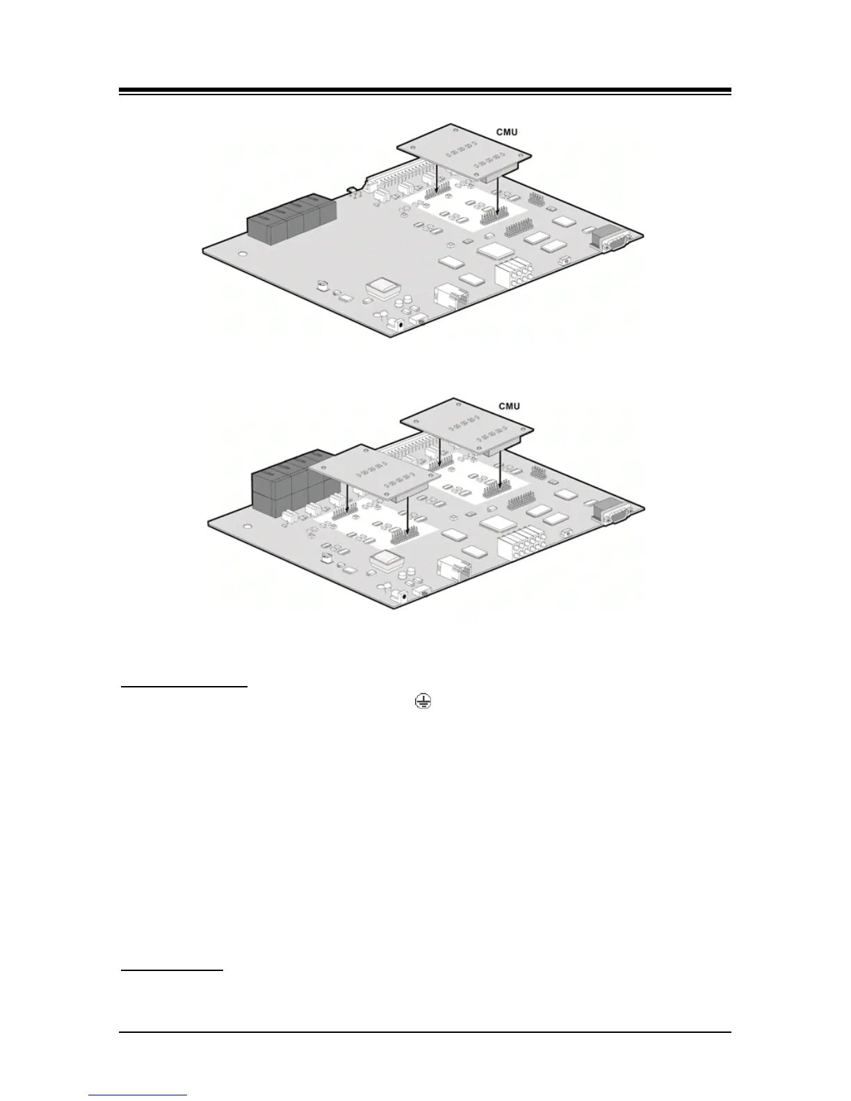
Figure 6.5-1 installing a CMU module in LGCM4
Figure 6.5-2 Installing a CMU module with LGCM8
Wiring Connectors
Before wiring any of the Modules, connect the “ ” screw on the back of the Module to a known
protective earth ground, refer to 6.1.4. If installed in a cabinet assure the cabinet is grounded.
On the front of the LGCM4 and LGCM8 is the RJ-45 type “LAN” connector. This connector should
be wired to the appropriate LAN points as discussed in 6.1.6 and 6.1.7.
Wire “LAN” to a 10/100 Base-T switch, ES8G/ES8GP can be used to connect to the LAN.
Tag or number wiring for maintenance.
On the rear are four (4) or eight (8) RJ-45 connectors, terminated as described in 6.1.5. These
connectors should be cabled to the telephone company termination point.
Wire each RJ-45 to a CO Line at the PSTN termination point/MDF.
Tag or number wiring for maintenance.
AC/DC Adapter
If a PSU is not employed, assure the AC/DC Adapter is plugged into a live AC outlet and the
Module Power jack.