@
. INSTALLATION (COMMON TO BOTH MODELS)
< Table >
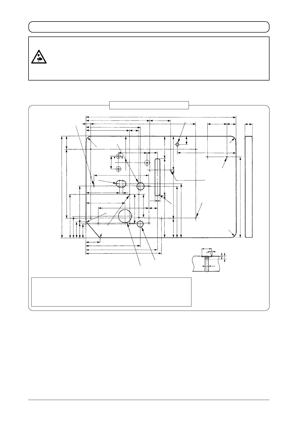
Arrange the relation of position between the table, motor, pneumatic components, etc. referring to the drawing of table below.
Drawing of table for reference
A
: Rubber cushion installing position (4 places)
B
: Position of wood screw for xing bobbin winder base (3 places)
C
: Position of wood screw for xing air unit (2 places)
D
: Position of wood screw for xing knee lifter unit (bottom surface) (4 places)
E
: Position of wood screw for xing table/stand (4 places)
Z-Z (3 places) Position of motor xing bolt
C
2×
φ
3.5 on the
bottom surface depth 10
E
4×
φ
3.5 on the
bottom surface depth 20
(For xing table/stand)
110
50
40
44
D
4×
φ
3.5 on the
bo tto m s ur fac e
depth 20
φ
40±0.5 drilled hole
A
4×
φ
3.5 depth 10
(Installing position of
rubber cushion)
240.5
70
360
535
351
116
830
24
300
580
49
Z
Z
227.7
114
85
78
74
195
75
298
393.3
414
278
φ
35 drilled hole
φ
70 drilled hole
213
183
20
R30
R30
R30
303
2×R 17.5
R30
325
R30
425
284
271
100
257
(178)
(120)
195220
4×R8
28
48.3
120.5
152
159
57
B
3×
φ
3.5 depth 10
φ
26
φ
8.5
30˚
8
1
66.5
140
φ
18 drilled hole
WARNING :
• Perform the installation of the sewing machine by the technical personnel who have been trained.
• To prevent personal injury, ask our dealer or the electrician for electric wiring.
• Be sure to perform the work with two persons or more when transporting the sewing machine and use a
lorry when moving it.
• To prevent personal injury caused by abrupt start of the sewing machine, do not connect the power plug
until the set-up of the sewing machine is completed.
• Be sure to earth the ground wire to prevent personal injury caused by leak.
• Be sure to attach safety protection cover, ger guard, etc.
 Loading...