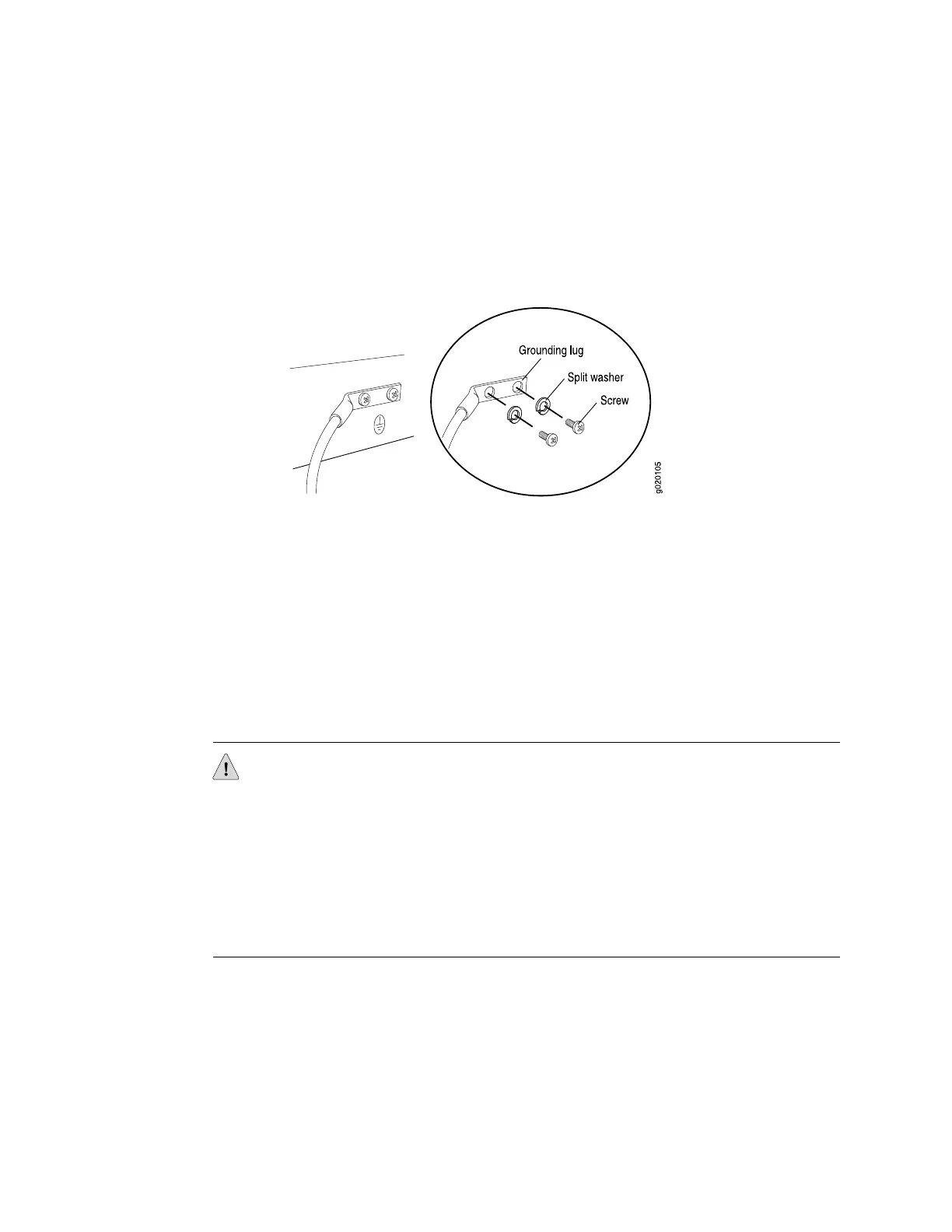
4. Place the grounding lug attached to the grounding cable over the protective
earthing terminal, as shown in Figure 41 on page 79.
5. Secure the grounding lug to the protective earthing terminal, first with the
washers, then with 10-32x.25 in. screws.
Figure 41: Connecting a Grounding Cable to an EX-series Switch
Related Topics ■ Connecting AC Power to an EX 3200 or EX 4200 Switch on page 79
■ Power Supply in EX 3200 and EX 4200 Switches on page 27
■ General Safety Guidelines and Warnings on page 130
■ Grounded Equipment Warning on page 163
Connecting AC Power to an EX 3200 or EX 4200 Switch
The power supply in an EX 3200 or EX 4200 switch is a hot-removable and
hot-insertable field-replaceable unit (FRU) located on the rear panel.
CAUTION: To meet safety and electromagnetic interference (EMI) requirements and
to ensure proper operation, you must connect EX 3200 and EX 4200 switches to
earth ground before you connect them to power. For installations that require a
separate grounding conductor to the chassis, use the protective earthing terminal on
the switch chassis to connect to the earth ground. For instructions on connecting
earth ground, see “Connecting Earth Ground to an EX-series Switch” on page 78. An
EX-series switch gets additional grounding when you plug the power supply in the
switch into a grounded AC power outlet by using the AC power cord appropriate for
your geographical location (see “AC Power, Connection, and Power Cord
Specifications” on page 56).
Ensure that you have the following parts and tools available to connect AC power to
an EX 3200 or EX 4200 switch:
■ Electrostatic discharge (ESD) grounding strap
■ Power cord appropriate for your geographical location
Before you begin connecting AC power to an EX 3200 or EX 4200 switch:
Connecting AC Power to an EX 3200 or EX 4200 Switch ■ 79
Chapter 3: Installing the Switch

 Loading...


