To connect DC power to an EX 3200 or EX 4200 switch:
1. Attach the electrostatic discharge (ESD) grounding strap to your bare wrist, and
connect the strap to the ESD point on the chassis.
2. Ensure that the power supplies are fully inserted in the chassis and the screws
on their faceplates are tightened.
3. Ensure that the input circuit breaker is open so that the voltage across the DC
power source cable leads is 0 V and that the cable leads will not become active
while you are connecting DC power.
NOTE: The DC power supply in EX 3200 and EX 4200 switches has four terminals
labeled A+, A–, B+, and B– (see Figure 44 on page 82) for connecting DC power
source cables labeled positive (+) and negative (–). The DC power supplies for EX
3200 and EX 4200 switches are shipped with jumpers from A+ input to B+ input
tied together and jumpers from A– input to B– input tied together.
NOTE: The A+ and B+ terminals are referred to as +RTN and A– and B– terminals
are referred to as –48 V in “DC Power Wiring Sequence Warning for EX 3200 and
EX 4200 Switches” on page 159 and “DC Power Electrical Safety Guidelines for EX
3200 and EX 4200 Switches” on page 157.
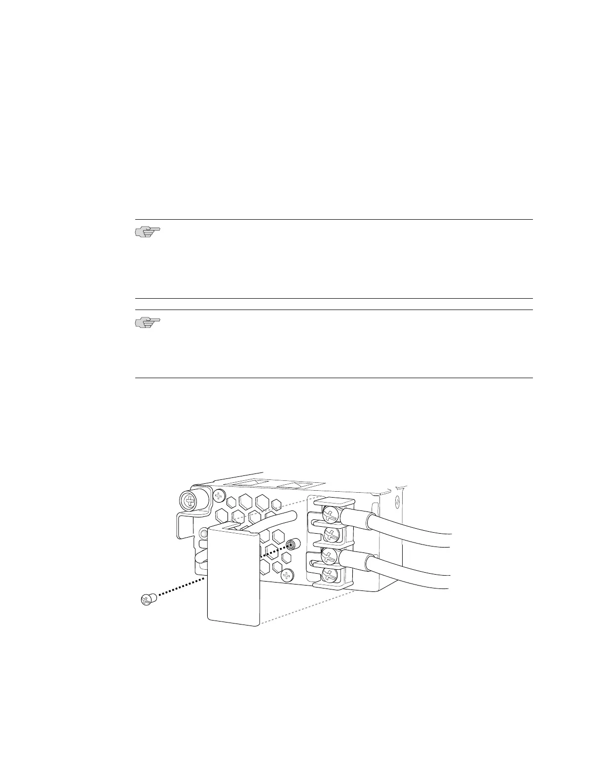
4. Remove the screw securing the terminal block cover using the
Phillips (+) screwdriver, number 2 and remove the terminal block cover (see
Figure 45 on page 83). Save the screw.
Figure 45: Removing the Terminal Block Cover in a DC Power Supply in EX 3200 and
EX 4200 Switches
5. Remove the screws on the terminals using the Phillips (+) screwdriver, number 2.
Save the screws.
Connecting DC Power to an EX 3200 or EX 4200 Switch ■ 83
Chapter 3: Installing the Switch

 Loading...


