■ Installing an SFP or XFP Transceiver in an EX-series Switch on page 104
■ Optical Interface Support—EX 3200 and EX 4200 Switches on page 21
■ Example: Configuring Aggregated Ethernet High-Speed Uplinks Between a Virtual
Chassis Access Switch and a Virtual Chassis Distribution Switch
■ Example: Configuring Aggregated Ethernet High-Speed Uplinks with LACP
Between a Virtual Chassis Access Switch and a Virtual Chassis Distribution Switch
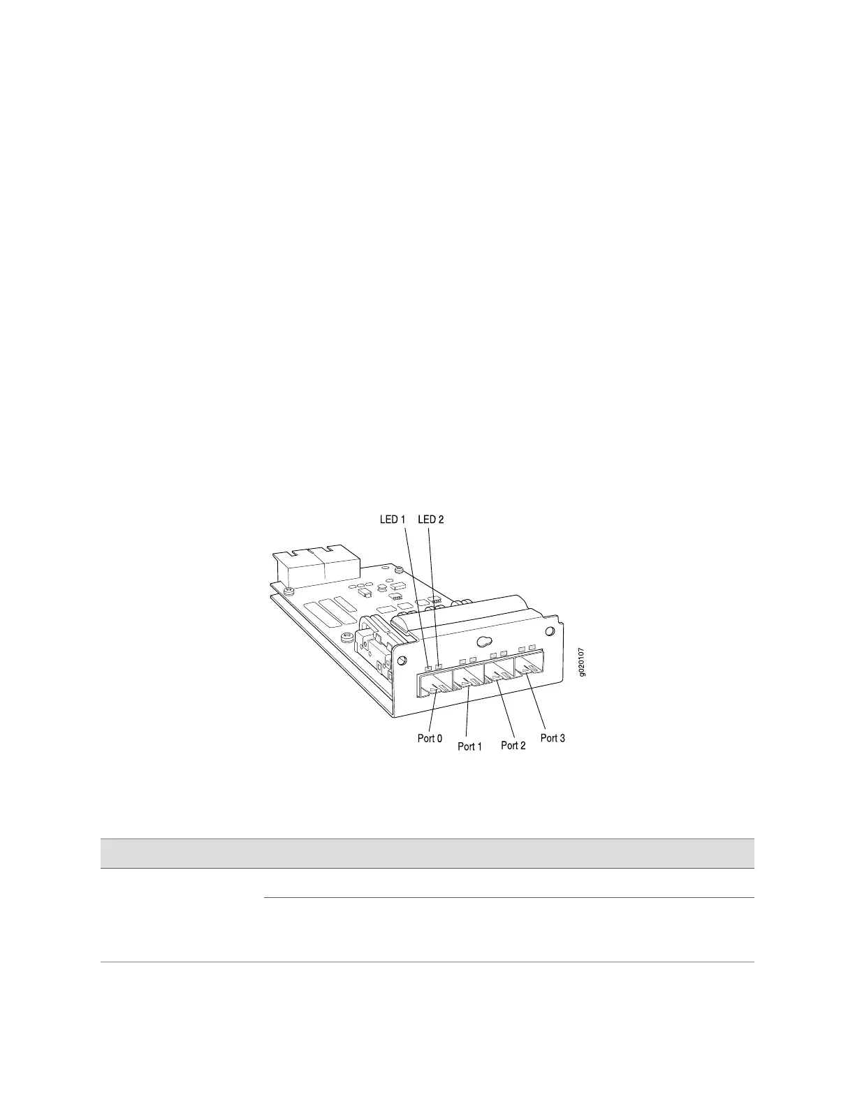
EX-series Switch—SFP Uplink Module Port LEDs
The ports on the small-form factor pluggable transceiver (SFP) uplink module have
two LEDs. Figure 13 on page 18 shows the SFP uplink module port and the location
of the LEDs on the port.
The LEDs labeled LED 1 in Figure 13 on page 18 indicate link status, and the LEDs
labeled LED 2 in Figure 13 on page 18 indicate the status of one of the four port
parameters. The port parameters are: administrative status; duplex mode; PoE status;
and speed.
Figure 13: EX-series Switch—SFP Uplink Module Port LEDs
Table 8 on page 18 describes LED 1.
Table 8: EX-series Switch—SFP Uplink Module Port LEDs–LED 1
State and DescriptionColorLED
No link activity.UnlitLED 1
■
On steadily—The port is up and the link is active, but
there is no link activity.
■
Blinking—The port is up, with active links.
Green
18 ■ EX-series Switch—SFP Uplink Module Port LEDs
Complete Hardware Guide for EX 3200 and EX 4200 Switches

 Loading...


