Figure 39: EX 4200 Switches Virtual Chassis—Mounted on Adjacent Racks and
Connected in a Ring Topology—Medium and Long Cables, Option 2
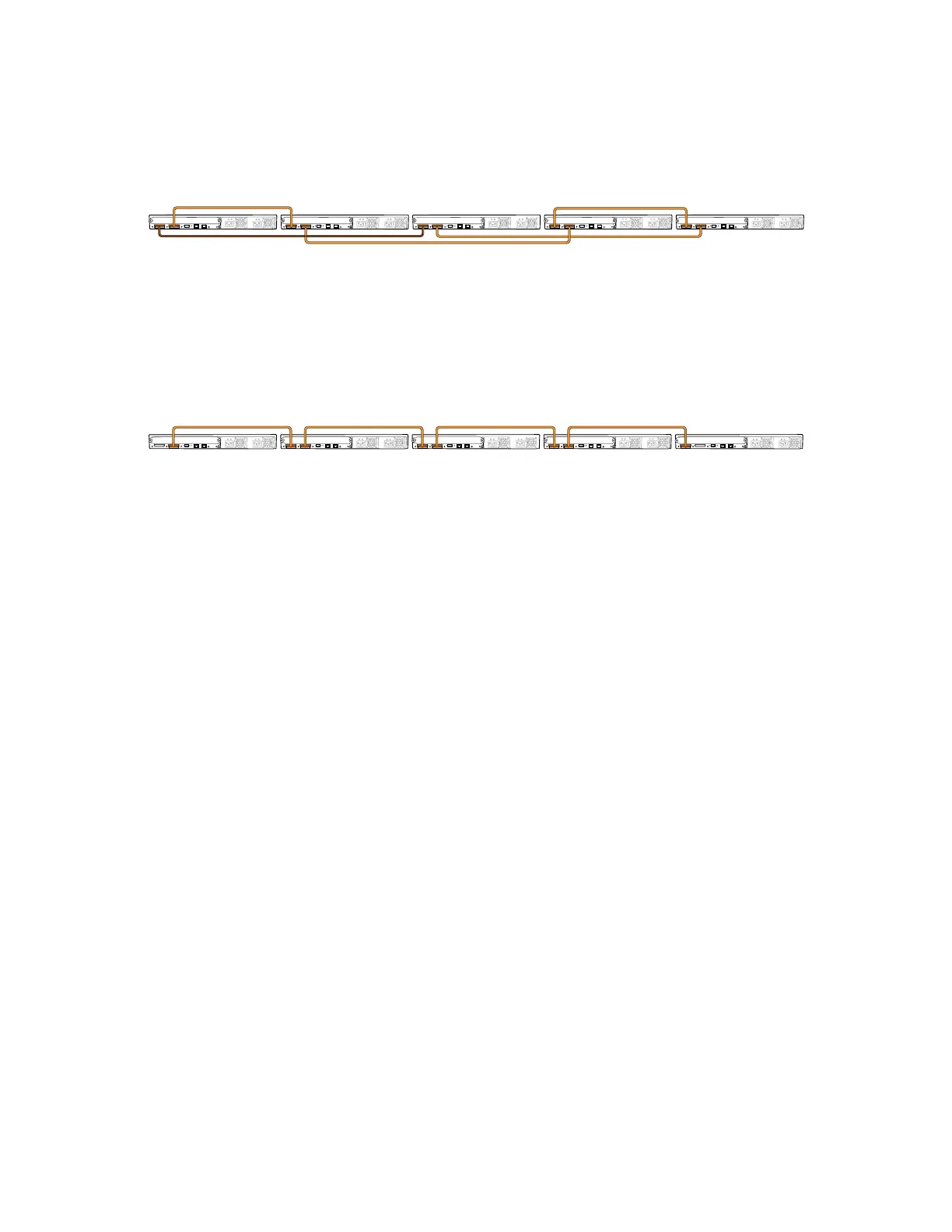
Figure 40 on page 75 shows five EX 4200 switches mounted on the top rows of
adjacent racks and interconnected in a chain topology using medium-length virtual
chassis cables.
Figure 40: EX 4200 Switches Virtual Chassis—Mounted on Adjacent Racks and
Connected in a Chain Topology—Medium Cables
Related Topics ■ Understanding Virtual Chassis Hardware Configuration on page 58
■ Understanding Virtual Chassis Components
■ Planning the Virtual Chassis on page 58
■ Virtual Chassis Ports Connector Pinout Information on page 42
■ Example: Configuring a Virtual Chassis Interconnected Across Multiple Wiring
Closets
Adding a New Switch to an Existing Virtual Chassis Configuration (CLI Procedure)
You can add one or more EX 4200 switches to an existing Virtual Chassis
configuration. Up to ten EX 4200 switches can be included within a Virtual Chassis
configuration.
To add a switch to an existing Virtual Chassis configuration, use the procedure that
matches what you need to accomplish:
■ Adding a New Switch to an Existing Virtual Chassis Configuration Within the
Same Wiring Closet on page 75
■ Adding a New Switch from a Different Wiring Closet to an Existing Virtual Chassis
Configuration on page 76
Adding a New Switch to an Existing Virtual Chassis Configuration Within
the Same Wiring Closet
Before you begin, be sure you have:
■ Installed the hardware components.
■ Mounted the new switch in a rack.
■ Confirmed that the new switch is powered off.
Adding a New Switch to an Existing Virtual Chassis Configuration (CLI Procedure) ■ 75
Chapter 3: Installing the Switch

 Loading...


