Related Topics ■ Installing a Power Supply in an EX-series Switch on page 107
■ Removing a Power Supply from an EX-series Switch on page 108
■ Installing a Fan Tray in an EX-series Switch on page 110
■ Removing a Fan Tray from an EX-series Switch on page 112
■ Installing an Uplink Module in an EX-series Switch on page 101
■ Removing an Uplink Module from an EX-series Switch on page 102
■ Installing an SFP or XFP Transceiver in an EX-series Switch on page 104
■ Removing an SFP or XFP Transceiver from an EX-series Switch on page 106
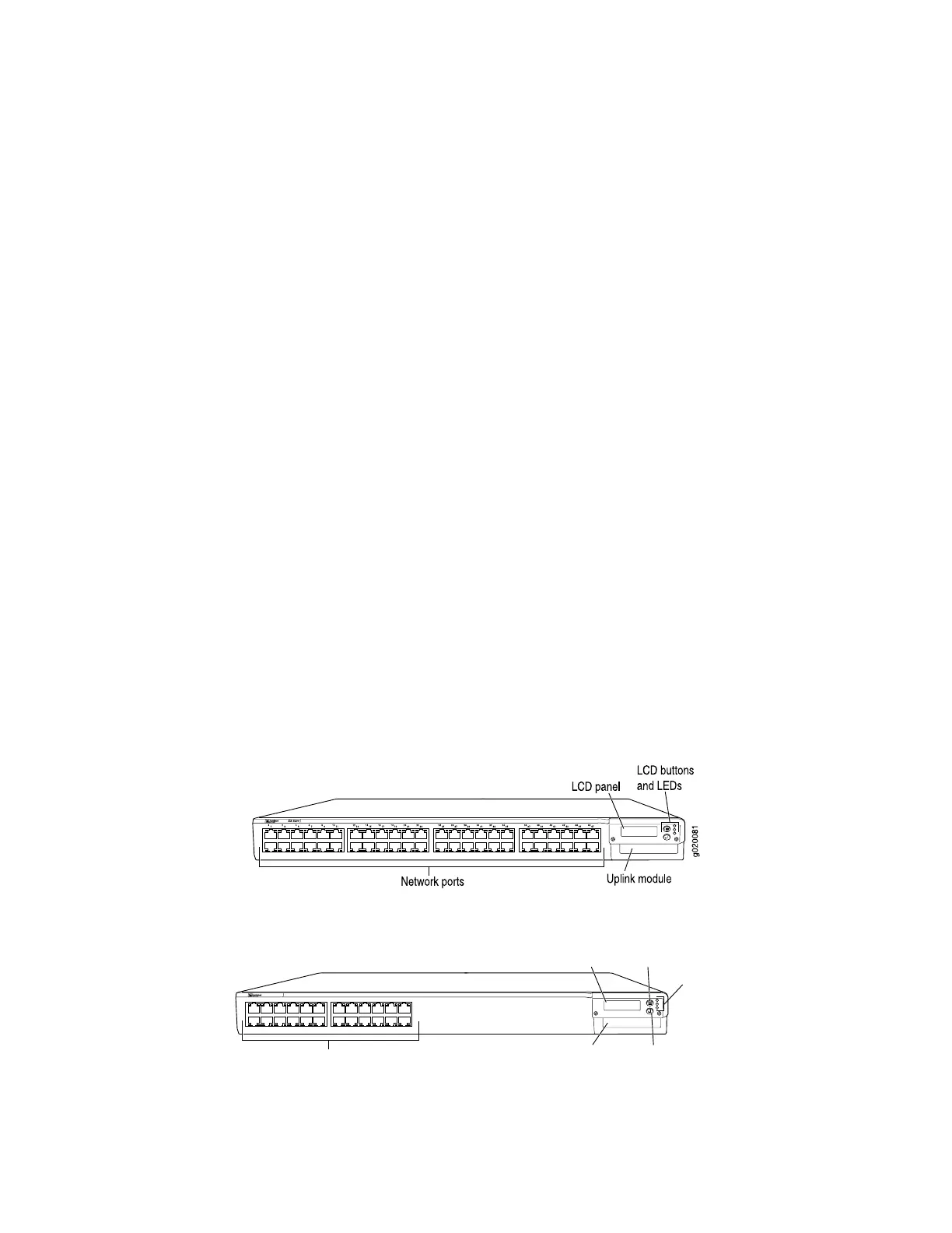
EX 3200 Switch—Front-Panel Description
The front panel of the EX 3200 switch consists of the following components:
■ 10/100/1000 Gigabit Ethernet ports, some or all of which are enabled for Power
over Ethernet (PoE)
■ Uplink module ports—SFP or XFP ports
■ LCD panel and the LCD navigation buttons
■ Front-panel LEDs
Figure 1 on page 9 shows the front panel of an EX 3200 switch with 48 Gigabit
Ethernet ports. Figure 2 on page 9 shows the front panel of an EX 3200 with 24
Gigabit Ethernet ports. Models are available that have either all ports equipped for
Power over Ethernet (PoE) or only 8 ports equipped for PoE. All ports have
10/100/1000 Base-T Gigabit Ethernet connectors.
Figure 1: EX 3200 Switch with 48 Gigabit Ethernet Ports
Figure 2: EX 3200 Switch with 24 Gigabit Ethernet Ports
EX 3200
0
1
2
3
4
5
6
7
8
9
10
11
12
13
14
15
16
17
18
19
20
21
22
23
g020054
Network ports
LCD panel
Uplink module
Menu button
Enter button
LEDs
ALM
SYS
MST
EX 3200 Switch—Front-Panel Description ■ 9
Chapter 1: Switch Overview

 Loading...


