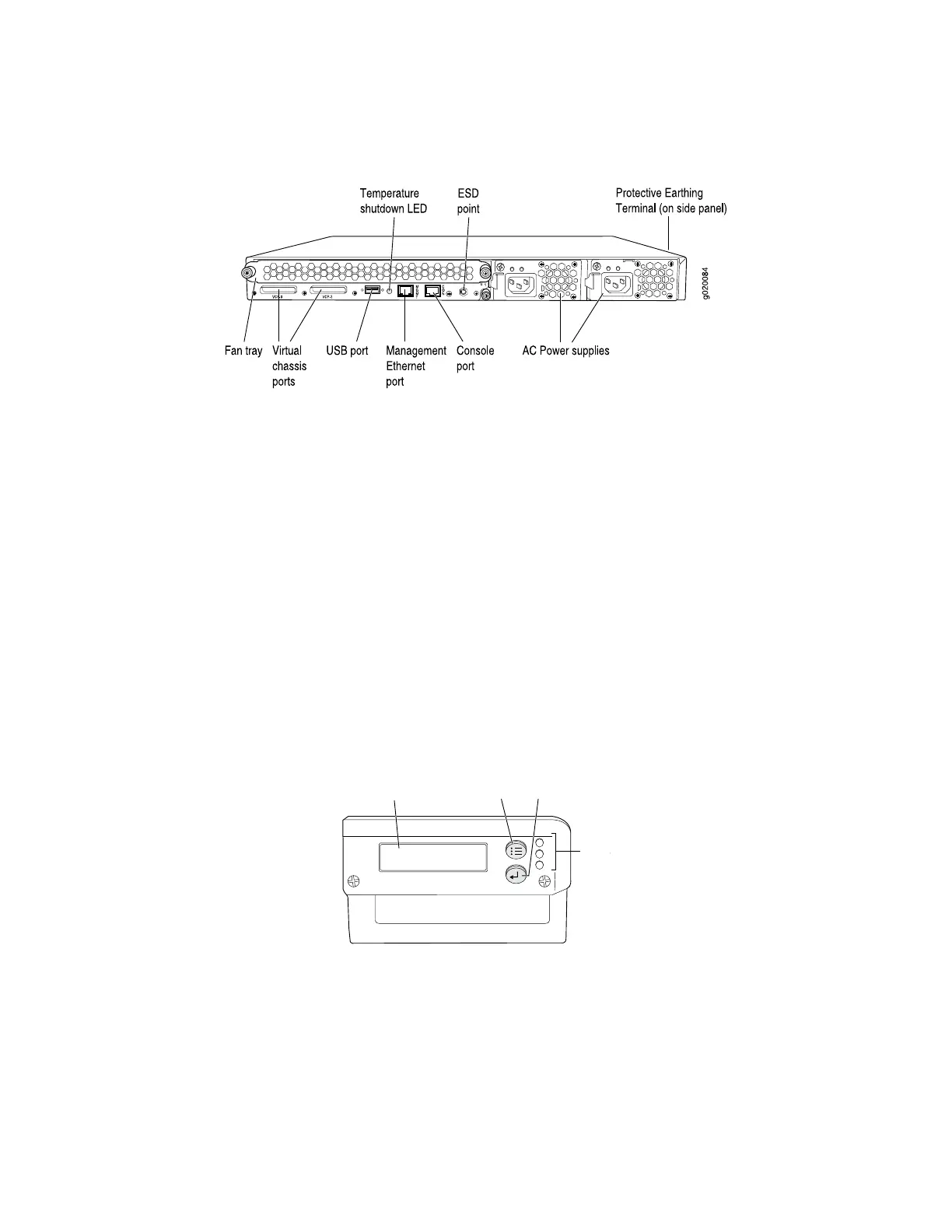
Figure 7: EX 4200 Switch Rear Panel
Related Topics ■ Field-Replaceable Units in EX-series Switches on page 99
■ USB Port Specifications for an EX-series Switch on page 26
■ Cooling System in an EX 4200 Switch on page 32
■ Power Supply in EX 3200 and EX 4200 Switches on page 27
■ Preventing Electrostatic Discharge Damage on page 138
■ Connecting Earth Ground to an EX-series Switch on page 78
■ Installing and Removing EX-series Switch Hardware Components on page 100
■ Understanding Virtual Chassis Hardware Configuration on page 58
EX 3200 Switch—Front-Panel LEDs
The front panel of an EX 3200 switch has three LEDs on the far right side of the
panel, next to the LCD (seeFigure 8 on page 13).
Figure 8: Front Panel LEDs in an EX 3200 Switch
g020093
LCD panel Menu button Enter button
LEDs
ALM
SYS
MST
Table 4 on page 14 describes the LEDs in an EX 3200 switch, their colors and state,
and the status they indicate.
EX 3200 Switch—Front-Panel LEDs ■ 13
Chapter 1: Switch Overview

 Loading...


