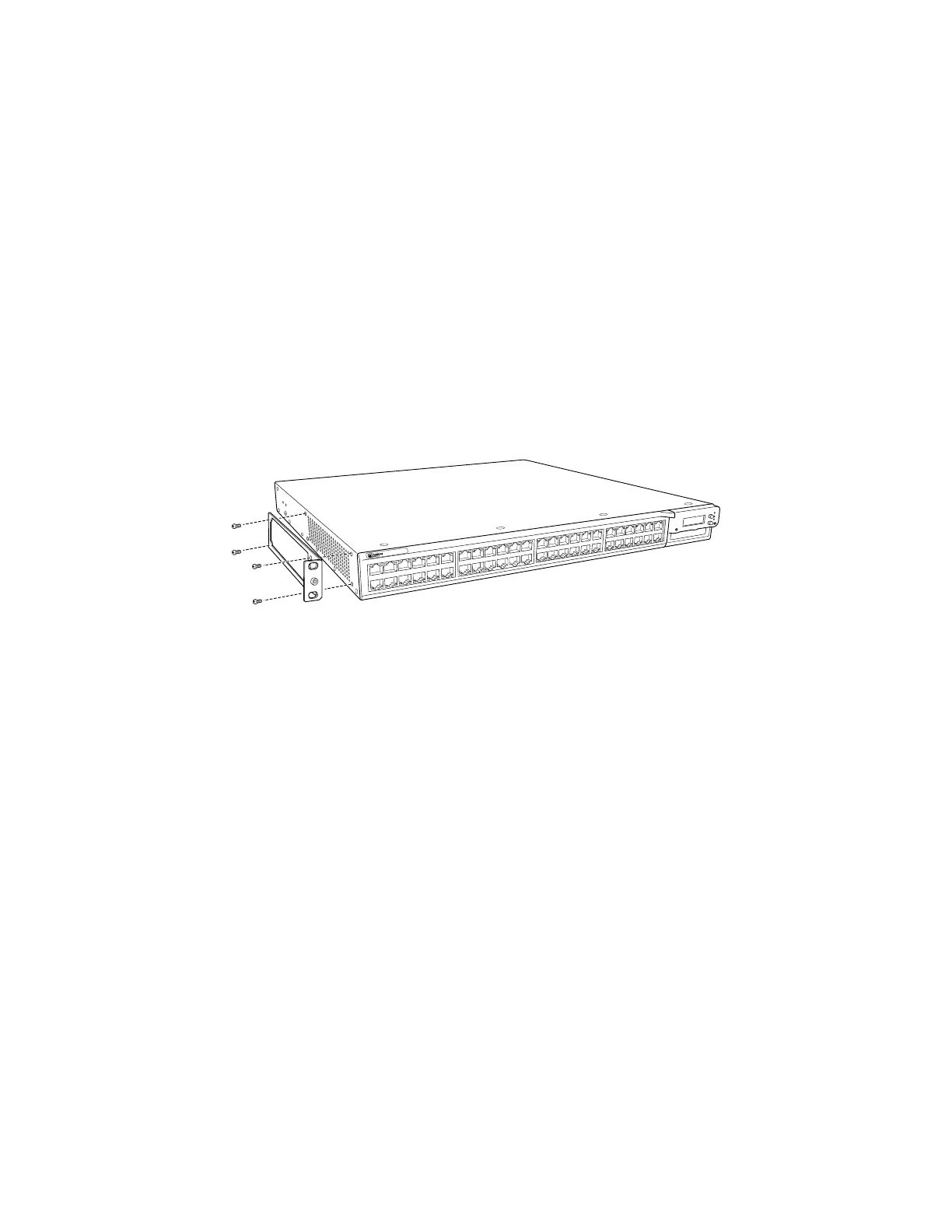
rack. Align the bottom hole in both the mounting brackets with a hole in each
rack or cabinet rail, making sure the chassis is level.
3. Insert one mounting screw (provided in the accessory box shipped with the
switch) into each of the two aligned holes. Use a Phillips (+) screwdriver,
number 2 to tighten the screws to the rack or cabinet rail.
4. Insert another screw into the other hole in each mounting bracket. Use a Phillips
(+) screwdriver, number 2 to tighten the screws to the rack or cabinet rail.
5. Verify that all the mounting screws on one side of the rack or cabinet are aligned
with the mounting screws on the other side and that the switch chassis is level.
6. If it is an EX 4200-24F switch, we recommend you insert dust covers in unused
SFP ports.
Figure 31: Attaching Mounting Brackets Along the Front of an EX-series Switch
68 ■ Mounting an EX-series Switch on a Rack or Cabinet
Complete Hardware Guide for EX 3200 and EX 4200 Switches

 Loading...


