Table 5: Front Panel LEDs in an EX 4200 Switch (continued)
State and DescriptionColorLED Label
■
On steadily—The switch is the master in the virtual
chassis configuration.
■
Blinking—The switch is the backup in the virtual chassis
configuration.
■
Off—The switch is a member (linecard member) in the
virtual chassis configuration.
GreenMST (Master)
Related Topics EX 4200 Switch—Front-Panel Description on page 11■
■ Power Supply in EX 3200 and EX 4200 Switches on page 27
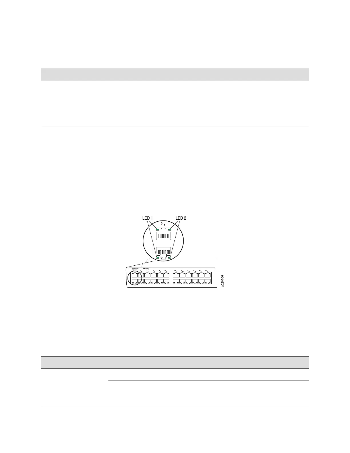
EX-series Switch—Network Port LEDs
Each network port on the front panel of an EX-series switch has two LEDs.
Figure 10 on page 25 shows the network ports and the locations of the LEDs on the
port.
Figure 10: EX-series Switch—Network Port LEDs
The LEDs to the left of the port opening (labeled LED 1 in Figure 10 on page 25)
indicate link activity. The LEDs to the right of the port opening (labeled LED 2 in
Figure 10 on page 25) indicate the status of one of the four port parameters. The
port parameters are: administrative status; duplex mode; PoE status; and speed.
Table 6 on page 15 describes LED 1.
Table 6: EX-series Switch—Network Port LEDs–LED 1
State and DescriptionColorLED
No link or no link activity.UnlitLED 1
■
On steadily—The port is up and the link is active, but
there is no link activity.
■
Blinking—The port is up, with active links.
Green
EX-series Switch—Network Port LEDs ■ 15
Chapter 1: Switch Overview

 Loading...


