■ Allow at least 6 in. (15.2 cm) of clearance on the side between devices that have
fans or blowers installed. Allow 2.8 in. (7 cm) between the side of the chassis
and any non-heat-producing surface such as a wall. For the cooling system to
function properly, the airflow around the chassis must be unrestricted.
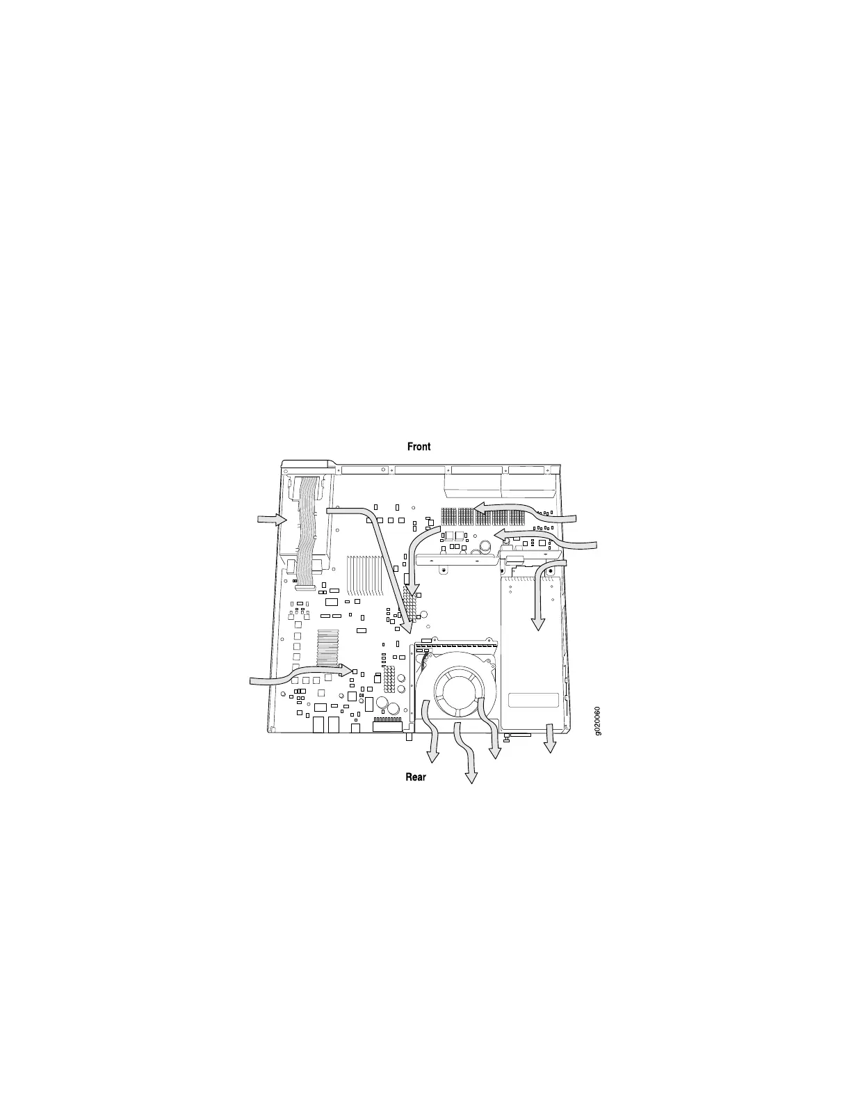
Figure 25 on page 53 shows the airflow through the EX 3200 switch chassis and
Figure 26 on page 54 shows the airflow through the EX 4200 switch chassis.
■ If you are mounting a switch in a rack or cabinet with other equipment, or if you
are placing it on the desktop or floor near other equipment, ensure that the
exhaust from other equipment does not blow into the intake vents of the chassis.
■ Leave at least 24 in. (61 cm) both in front of and behind the switch. For service
personnel to remove and install hardware components, you must leave adequate
space at the front and back of the switch. NEBS GR-63 recommends that you
allow at least 30 in. (76.2 cm) in front of the rack or cabinet and 24 in. (61 cm)
behind the rack or cabinet.
Figure 25: Airflow Through the EX 3200 Switch Chassis
Clearance Requirements for Airflow and Hardware Maintenance ■ 53
Chapter 2: Preparing the Site for Switch Installation

 Loading...


