Related Topics ■ EX 3200 Switch—Front-Panel LEDs on page 13
■ EX-series Switch—LCD on page 24
■ EX-series Switch—Network Port LEDs on page 15
■ Installing and Removing EX-series Switch Hardware Components on page 100
■ Installing an Uplink Module in an EX-series Switch on page 101
■ Removing an Uplink Module from an EX-series Switch on page 102
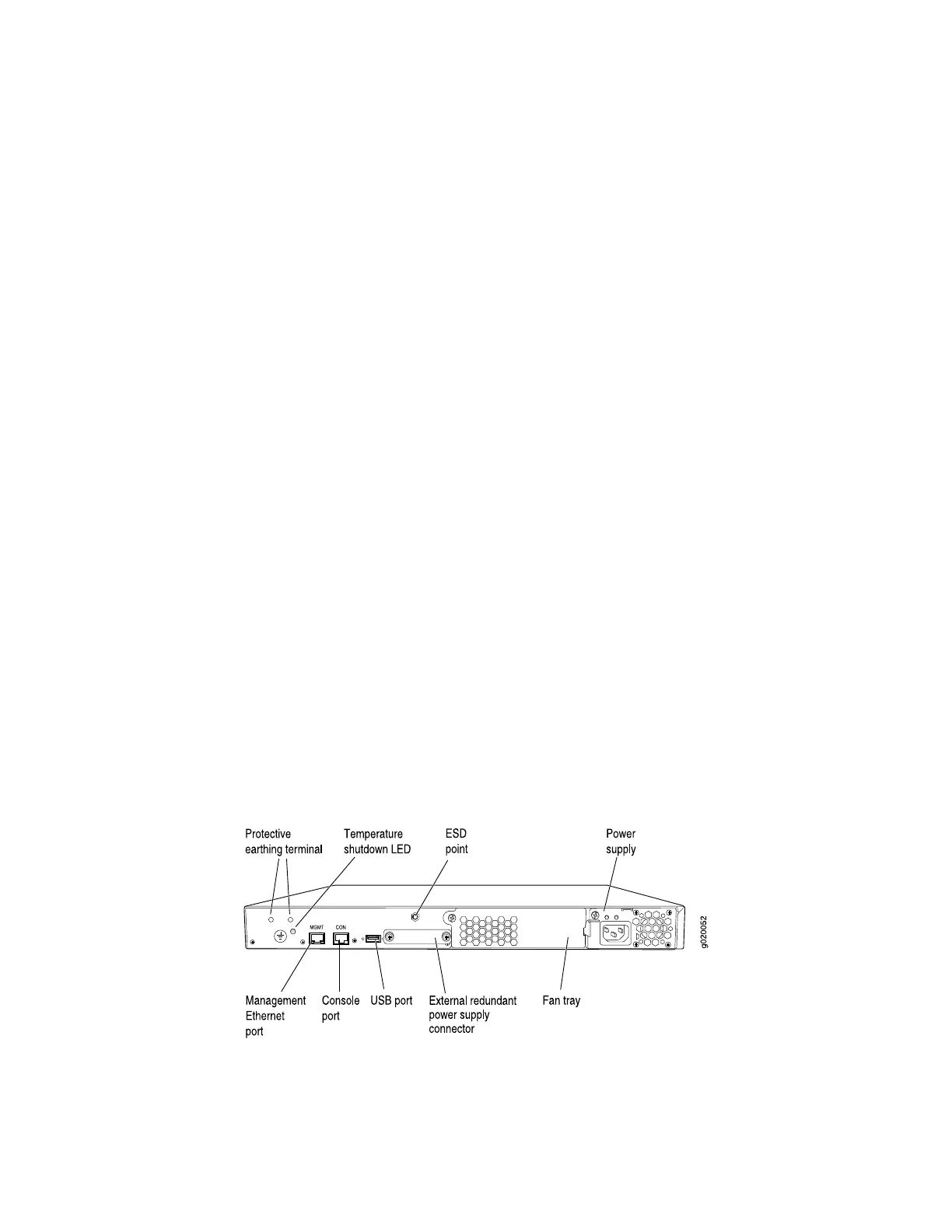
EX 3200 Switch—Rear-Panel Description
The rear panel of the EX 3200 switch consists of the following components:
■ Protective earthing terminal
■ Temperature shutdown LED
■ Management Ethernet port
■ Console port
■ USB port
■ ESD point
■ Fan tray
■ External redundant power supply connector
■ Power supply
Figure 3 on page 10 shows the rear panel of an EX 3200 switch with a 320 W power
supply. All switches in the EX 3200 series have the same rear panel. The 320 W
power supply is flush with the chassis. The 600 W power supply and 930 W power
supply extend out of the chassis by 2.25 inches. The power cord retainer clips extend
out of the power supply by 3 inches.
Figure 3: EX 3200 Switch Rear Panel
Related Topics ■ Field-Replaceable Units in EX-series Switches on page 99
■ USB Port Specifications for an EX-series Switch on page 26
10 ■ EX 3200 Switch—Rear-Panel Description
Complete Hardware Guide for EX 3200 and EX 4200 Switches

 Loading...


