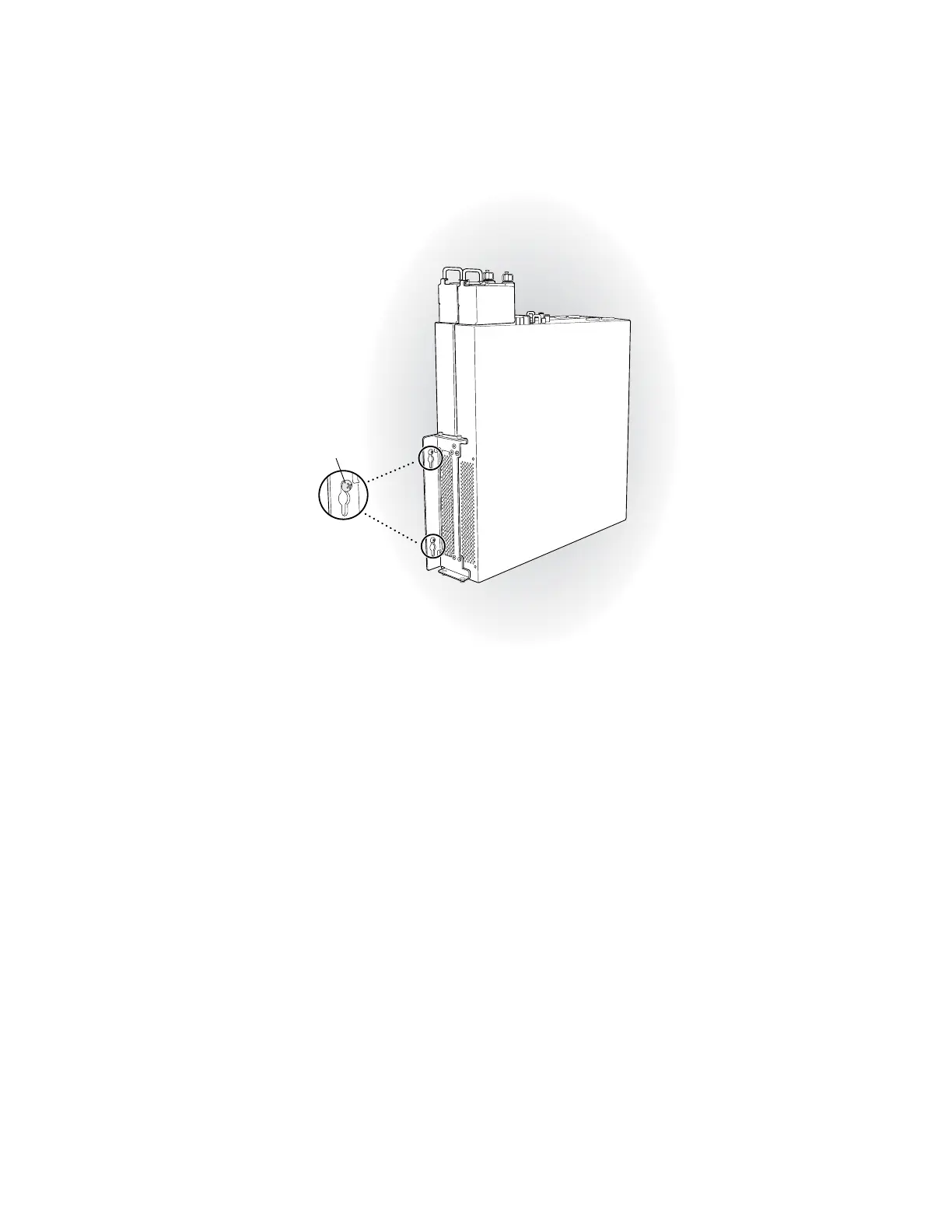
Figure 34: Mounting the EX-series Switch on the Wall
Hang attached brackets
on wall-mounted screws.
g020201
5. Tighten the mounting screws.
6. If it is an EX 4200-24F switch, we recommend you insert dust covers in unused
SFP ports.
Related Topics ■ Connecting AC Power to an EX 3200 or EX 4200 Switch on page 79
■ Connecting and Configuring the EX-series Switch (CLI Procedure) on page 91
■ Connecting and Configuring the EX-series Switch (J-Web Procedure) on page 92
■ Wall-Mounting Requirements and Warnings on page 151
Virtual Chassis Cabling Configuration Examples
You can install EX 4200 switches in a single rack or multiple racks, or in different
wiring closets, and interconnect them to form a virtual chassis. There are two
dedicated virtual chassis ports (VCPs) on the rear panel of the EX 4200 switch that
are used exclusively to interconnect EX 4200 switches as a virtual chassis. The
physical location of the switches in a virtual chassis is restricted only by the maximum
length supported for cables to connect the VCPs. The maximum cable length for
interconnecting the dedicated VCPs is 3 meters. If you want to interconnect EX 4200
switches that are located beyond the reach of the dedicated VCP cables, you can
install the EX-UM-2XFP uplink module and set the uplink ports as VCP interfaces.
See Setting an Uplink Port as a Virtual Chassis Port (CLI Procedure).
72 ■ Virtual Chassis Cabling Configuration Examples
Complete Hardware Guide for EX 3200 and EX 4200 Switches

 Loading...


