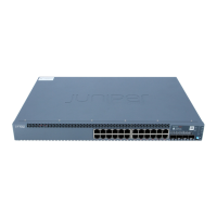
Table 25: Rack Requirements and Specifications for an EX-series Switch
GuidelinesRack Requirement
Use a front-mount rack, four-post (telco) rack, or a center-mount rack.Rack type
■
Ensure that the rack complies with one of these standards:
■
A 19-in. rack as defined in Cabinets, Racks, Panels, and Associated Equipment (document
number EIA-310–D) published by the Electronics Industry Association (http://www.eia.org).
■
A 600-mm rack as defined in the four-part Equipment Engineering (EE); European
telecommunications standard for equipment practice (document numbers ETS 300 119-1
through 119-4) published by the European Telecommunications Standards Institute
(http://www.etsi.org).
The horizontal spacing between the rails in a rack that complies with this standard is
usually wider than the switch's mounting brackets, which measure 19 in. (48.2 cm) from
outer edge to outer edge. Use approved wing devices to narrow the opening between the
rails as required.
■
Ensure that the rack rails are spaced widely enough to accommodate the switch chassis' external
dimensions. See Table 26 on page 51.
■
Ensure that the spacing of rails and adjacent racks allows for the proper clearance around the
switch and rack.
Rack size and strength
■
Secure the rack to the building structure.
■
If earthquakes are a possibility in your geographical area, secure the rack to the floor.
■
Secure the rack to the ceiling brackets as well as wall or floor brackets if maximum stability is
required.
Rack connection to
building structure
One pair of mounting brackets is supplied with the EX-series switch. The holes in
the mounting brackets are spaced at 1 U (1.75 in. or 4.445 cm), so the switch can
be mounted in any rack that provides holes spaced at that distance.
The outer edges of the mounting brackets extend the width of either chassis to 19 in.
(48.2 cm), and the front of the chassis extends approximately 0.5 in. (1.27 cm)
beyond the mounting brackets. The spacing of rails and adjacent racks must also
allow for the clearances around the switch and rack.
Table 26: EX-series Switches—External Dimensions
DimensionsSwitch Model
1.75 in. (4.445 cm) high, 17.25 in. (43.815 cm), and 17 in. (43.18 cm)
deep.
EX 3200, EX 4200 (without mounting brackets)
1.75 in. (4.445 cm) high, 17.25 in. (43.815 cm), and 19 in. (48.2 cm)
deep.
EX 3200, EX 4200 (with mounting brackets)
Related Topics EX-series Switch Chassis Physical Specifications on page 7■
■ Rack-Mounting Requirements and Warnings on page 147
■ Clearance Requirements for Airflow and Hardware Maintenance on page 52
Rack Requirements and Specifications for an EX-series Switch ■ 51
Chapter 2: Preparing the Site for Switch Installation

 Loading...


