NOTE: The interfaces for the two dedicated VCPs are operational by default. However,
if you are using the uplink module ports as VCPs, you must explicitly set the uplink
ports to function as VCPs.
The following illustrations describe various cabling configuration examples. The
available bandwidth varies depending on the type of topology.
NOTE: A ring topology in a virtual chassis configuration provides up to 128 Gbps of
bandwidth between member switches. In a chain topology virtual chassis
configuration, the bandwidth is limited to 64 Gbps between two member switches.
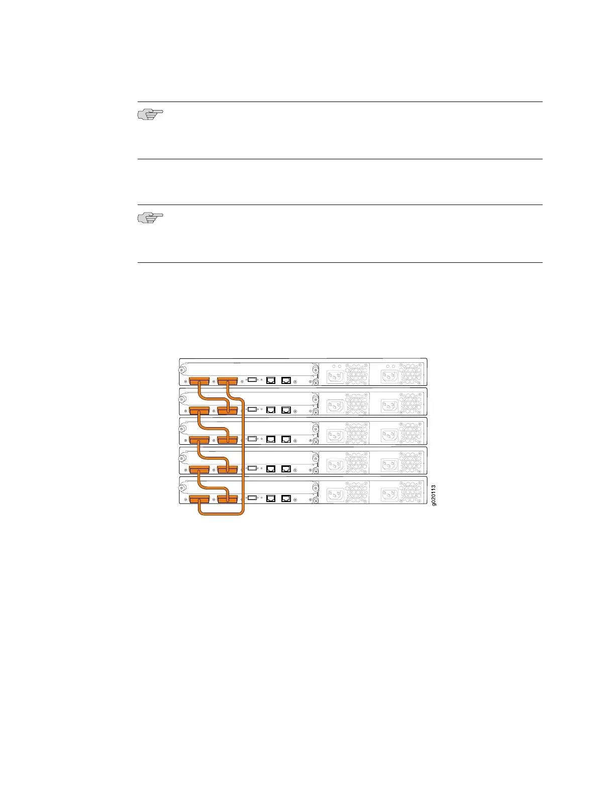
Figure 35 on page 73 and Figure 36 on page 74 show five EX 4200 switches stacked
vertically in a rack and interconnected in a ring topology using four short virtual
chassis cables and one long virtual chassis cable.
Figure 35: EX 4200 Switches Virtual Chassis—Mounted on a Single Rack and
Connected in a Ring Topology—Short and Long Cables, Option 1
Virtual Chassis Cabling Configuration Examples ■ 73
Chapter 3: Installing the Switch

 Loading...


