EX-series Switch—Management Port Connector Pinout Information
The management port on the rear panel of an EX-series switch chassis has an RJ-45
connector. Table 21 on page 35 provides the pinout information of the RJ-45
connector. An RJ-45 cable is supplied with the switch.
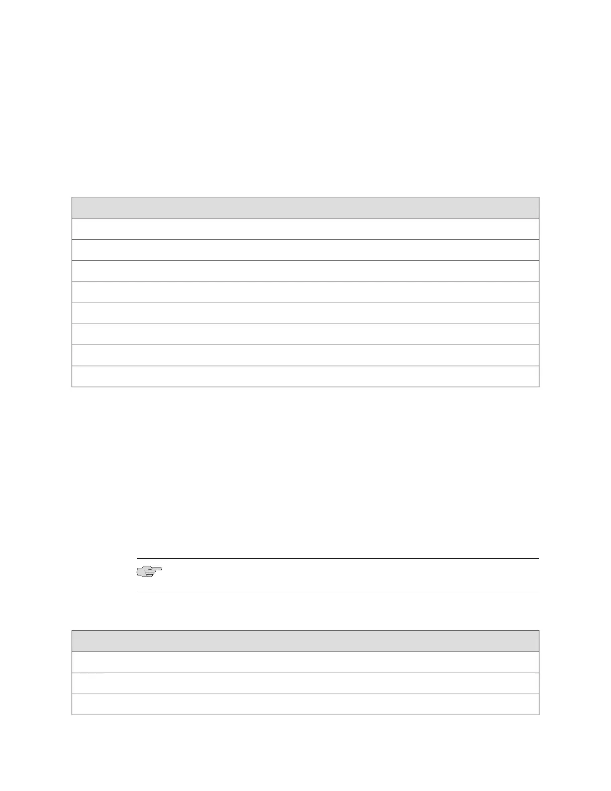
Table 21: Management Port Connector Pinout Information
DescriptionSignalPin
Transmit dataTX+1
Transmit dataTX-2
Receive dataRX+3
Termination network4
Termination network5
Receive dataRX-6
Termination network7
Termination network8
Related Topics ■ EX 3200 Switch—Rear-Panel Description on page 10
■ EX 4200 Switch—Rear-Panel Description on page 12
■ Virtual Chassis Ports Connector Pinout Information on page 42
■ Uplink Modules Connector Pinout Information on page 35
■ EX-series Switch—Console Port Connector Pinout Information on page 34
Uplink Modules Connector Pinout Information
EX-series switches have a field-replaceable unit (FRU) uplink module on the front
panel. Table 22 on page 35 provides the uplink modules connector pinout information.
NOTE: You can use the ports in the uplink modules as virtual chassis ports.
Table 22: Uplink Modules Connector Pinout Information
Pin NamePin Number
GNDA1
GNDA2
GNDA3
EX-series Switch—Management Port Connector Pinout Information ■ 35
Chapter 1: Switch Overview

 Loading...


