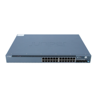
■ Remove the switch from the shipping carton (see “Unpacking an EX-series
Switch” on page 62).
■ Ensure you have the following tools and parts available:
■ Phillips (+) screwdriver, number 2
■ 2 wall-mount brackets
■ 12 wall-mount bracket screws
■ 4 mounting screws (8-32 x 1.25 inch or M4 x 30 mm) (not included)
■ Dust covers for ports (for EX 4200-24F switches only; optional)
■ Hollow wall anchors capable of supporting the combined weight of two
fully-loaded switches, up to 44 lb (20 kg) (not included)—if you are mounting
the switch in sheetrock (wall board with a gypsum plaster core) or in wall
board not backed by wall studs
■ Verify that there is appropriate clearance in your selected location (see “Clearance
Requirements for Airflow and Hardware Maintenance” on page 52).
WARNING: When mounted in a vertical position, an EX 3200 or EX 4200 chassis
must be oriented with the front panel of the chassis pointing down in order to ensure
proper air flow and meet safety requirements in the event of a fire.
NOTE: For easier lifting, install any additional power supplies only after you mount
the switch on the wall.
To mount the EX-series switch on a wall:
70 ■ Mounting an EX 3200 or EX 4200 Switch on a Wall
Complete Hardware Guide for EX 3200 and EX 4200 Switches

 Loading...


