Table 7: Management Port LEDs (continued)
DescriptionLED
•
Solid green—100-Mbps link is established.
•
Solid amber—1000-Mbps link is established.
•
Off—There is no link established.
Speed
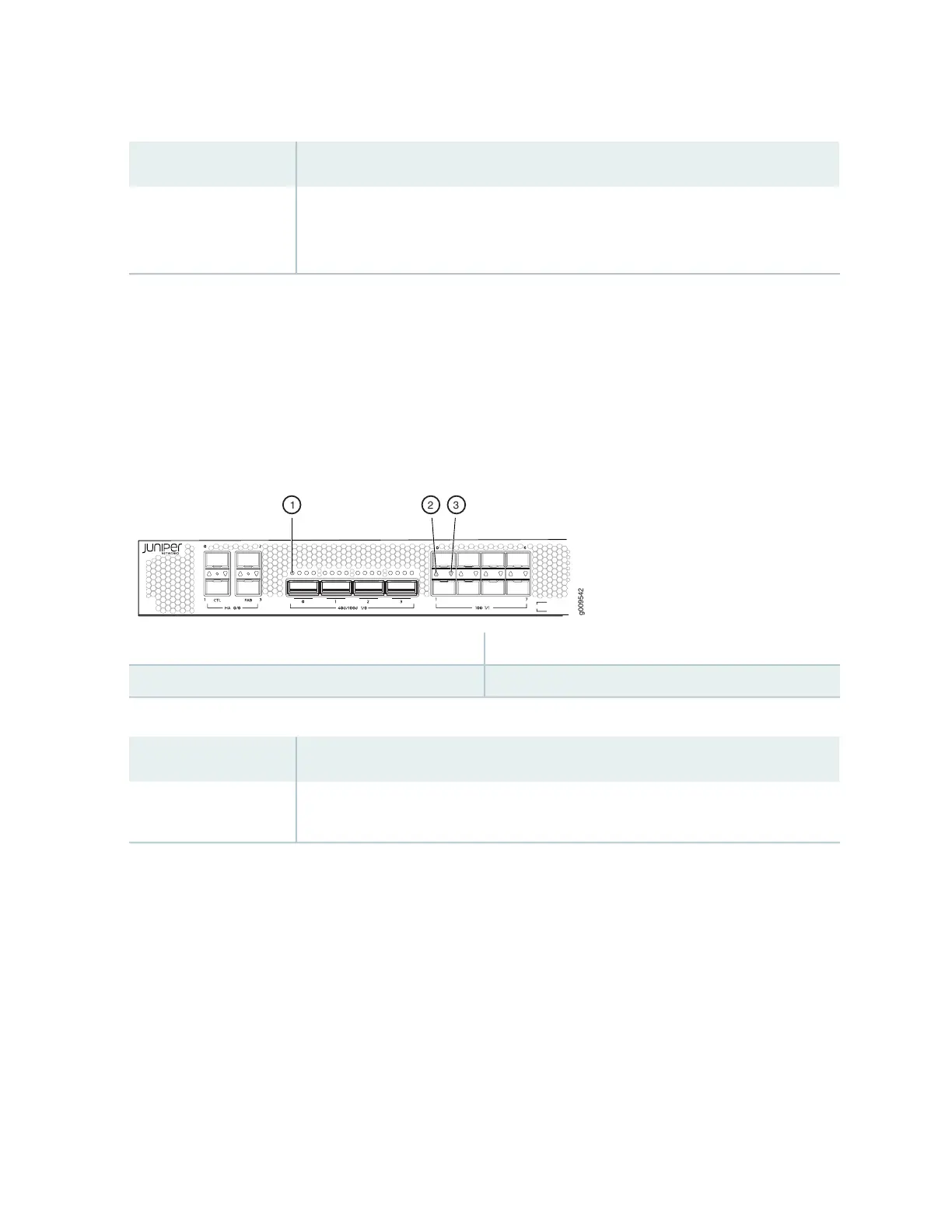
Network Port LEDs
Each QSFP28 port has one link activity LED above it and each SFP+ port has one link activity LED located
above or below it. Figure 8 on page 29 shows the location of the LEDs and Table 8 on page 29 describes
the LEDs.
Figure 8: Network Port LEDs
3—1— Link activity LED of SFP+ port 1Link activity LED of QSFP28 port 0
2—Link activity LED of SFP+ port 0
Table 8: Network Port LEDs
DescriptionLED
•
Solid green—There is link activity.
•
Off—There is no link established.
Link activity LED
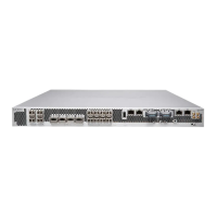
Port and Interface Numbering
Each port on the services gateway corresponds to a unique interface name in the CLI. The four Chassis
cluster (HA) ports (referred to as PIC 0 ports of FPC 0), four 40/100-Gigabit Ethernet QSFP28 (quad small
form-factor pluggable) ports (referred to as PIC 0 ports of FPC 1), and eight 1/10-Gigabit Ethernet SFP+
ports (referred to as PIC 1 ports of FPC 1). Figure 9 on page 30 shows the SRX4600 Interface Port
numbering.
In the syntax of an interface name, a hyphen (-) separates the media type from the FPC slot number
(represented as an FPC in the CLI). The FPC slot number corresponds to the first number in the interface.
The second number in the interface corresponds to the PIC number. The last number in the interface
29