plant, you can use a multimeter to verify the resistance of the –48V and RTN DC cables to chassis
ground:
•
The cable with very high resistance (indicating an open circuit) to chassis ground is negative (–) and
will be installed on the –48V (input) DC power input terminal.
•
The cable with very low resistance (indicating a closed circuit) to chassis ground is positive (+) and
will be installed on the RTN (return) DC power input terminal.
CAUTION: You must ensure that power connections maintain the proper
polarity. The power source cables might be labeled (+) and (–) to indicate their
polarity. There is no standard color coding for DC power cables. The color coding
used by the external DC power source at your site determines the color coding
for the leads on the power cables that attach to the DC power input terminals
on each power supply.
4. Remove the protective cover from the DC power input terminal block. Save this cover for future use.
NOTE: It might be necessary to slide each power supply partially out of the chassis to
easily connect the DC power source cables to the DC power input terminals. See “Removing
the SRX4600 Services Gateway DC Power Supply” on page 95.
5. Remove the M5 K-nuts from each DC power input terminal.
6. Attach DC terminal rings (TE 2-36161-2 Terminal Ring, number 10 or equivalent, provided) to the ends
of the DC power source cables (not provided). Crimp tightly.
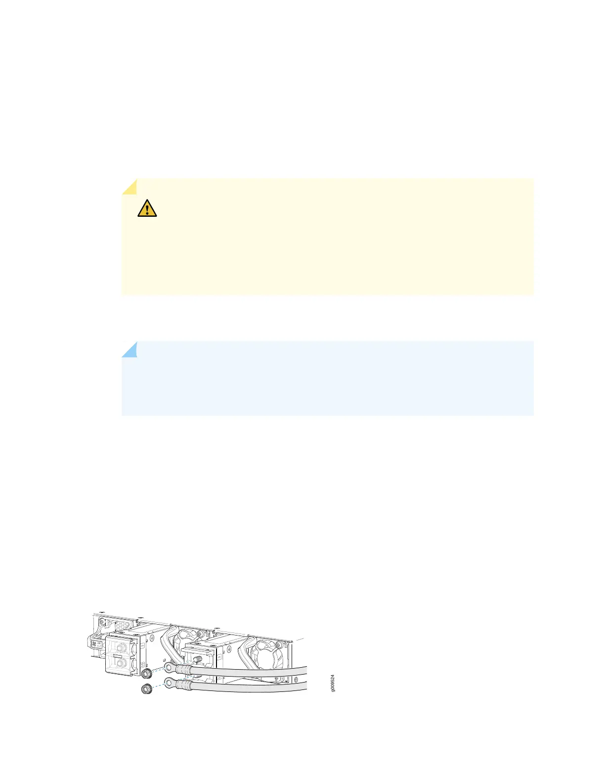
7. Insert the DC terminal rings into the DC power input terminals and secure the DC terminal rings with
M5 K-nuts, (see Figure 31 on page 79). Apply between 9 lb-in. (1.1 Nm) and 12 lb-in. (1.3 Nm) of torque
to tighten each M5 K-nuts.
Figure 31: Connecting the Power Supply Cables to a DC power Supply
79
 Loading...