- Digital Microscope VHX-5000 User’s Manual -
3D Profile Measurements (Optional)
10-24
Observing in 3D
3D Profile Measurements (Optional)
3D measurements allow you to check cross-sections of 3D images, and measure distances and angles.
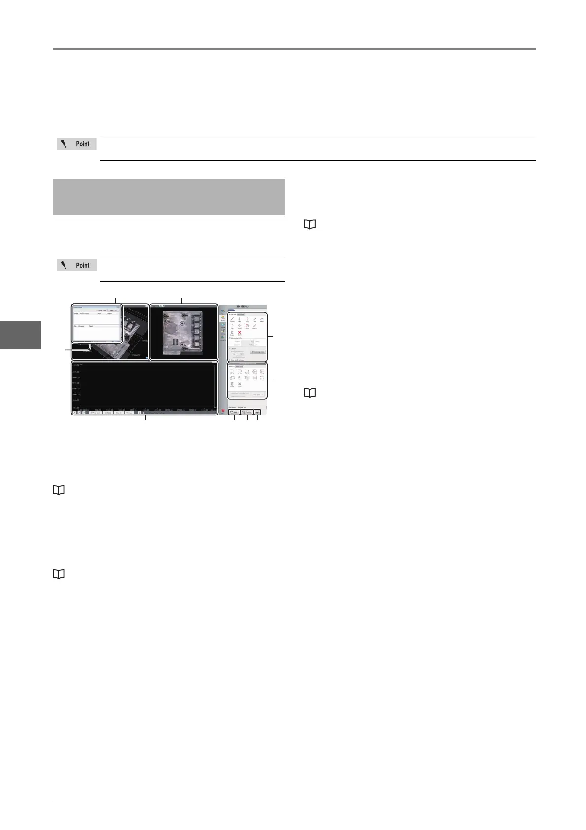
This section explains the names and functions of each part
of the window used to measure 3D profiles.
(1) Measurement results
Lists profiles and elements placed on the image and
measurement results.
"Profile/Measurement List" (Page 10-25)
(2) 3D display area
Displays a stereoscopic shape of the target object and the
cross section of the selected profile. You can change and
manipulate the 3D image display.
"Manipulating the 3D View" (Page 10-15)
(3) Image display area
Displays an image of the target object when you see it
perpendicular to the reference plane. You can set a profile
line on this image. You can also change the display type of
the image.
(4) Profile tool
Contains buttons to draw various profile lines, such as a
straight line or a circle.
(5) Measurement tool
Buttons used to measure the interval specified by the profile
are displayed.
(6) Profile display area
Displays the profile graph for the profile line (or for the
selected profile line for the multi-line ) on the image.
"Profile Display Area" (Page 10-25)
(7) Save
Saves the current display as a 2D image.
(8) Option
Displays the [Option] dialog box.
• Sets the scale line, scale auxiliary line and background
color.
•Sets the unit (m/mm/m/in/mil) and number of decimals.
(9) Print
Displays the print menu.
"P
r
int Settings" (Page 12-2)
The separately sold “3D Profile Measurement Application” (model VHX-H4M) is required to perform 3D profile
measurements. Make sure this application is installed beforehand.
Names and Functions in the
Window
The content of the display will vary based on
the function being used.
(4)
(5)
(1)
(7) (8)
(6)
(3)(2)
(9)
 Loading...