3-38 Keysight B2961A/B2962A User’s Guide, Edition 3
Installation
Using Digital I/O
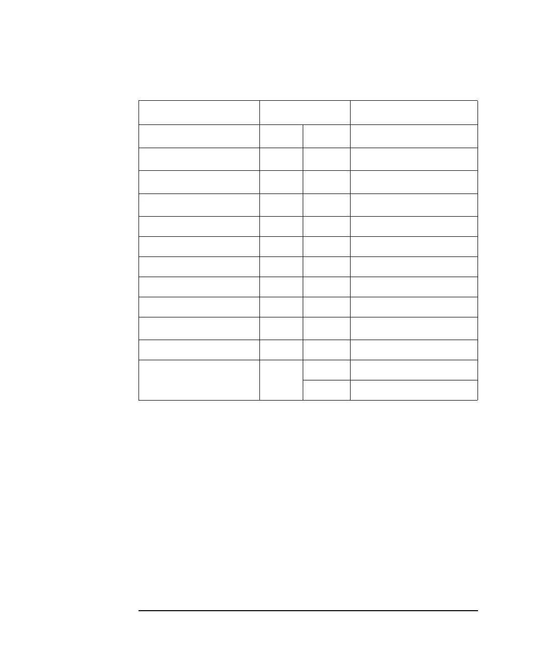
Table 3-1 Digital I/O Pin Assignment
Description Pin Number Description
+5 V
a
a. Current limit: 600 mA (total current to the pins 22, 23, and 25)
25 13 DIO 13 (bit 13)
Interlock control
b
b. Used for the positive logic. Connected to the pin 25 for the negative
logic.
24 12 DIO 12 (bit 12)
+5 V
a
23 11 DIO 11 (bit 11)
+5 V
a
22 10 DIO 10 (bit 10)
GND 21 9 DIO 9 (bit 9)
GND 20 8 DIO 8 (bit 8)
GND 19 7 DIO 7 (bit 7)
GND 18 6 DIO 6 (bit 6)
GND 17 5 DIO 5 (bit 5)
Interlock control
c
c. Used for the negative logic. Connected to the pin 17 for the positive
logic.
16 4 DIO 4 (bit 4)
GND 15 3 DIO 3 (bit 3)
DIO 14 (bit 14) or
High voltage status
14 2 DIO 2 (bit 2)
1 DIO 1 (bit 1)