116 Keysight InfiniiVision 2000 X-Series Oscilloscopes User's Guide
6 Digital Channels
Increasing the ground inductance (L), increasing the current (di) or decreasing the
transition time (dt), will all result in increasing the voltage (V). When this voltage
exceeds the threshold voltage defined in the oscilloscope, a false data
measurement will occur.
Sharing one probe ground with many probes forces all the current that flows into
each probe to return through the same common ground inductance of the probe
whose ground return is used. The result is increased current (di) in the above
equation, and, depending on the transition time (dt), the common mode voltage
may increase to a level that causes false data generation.
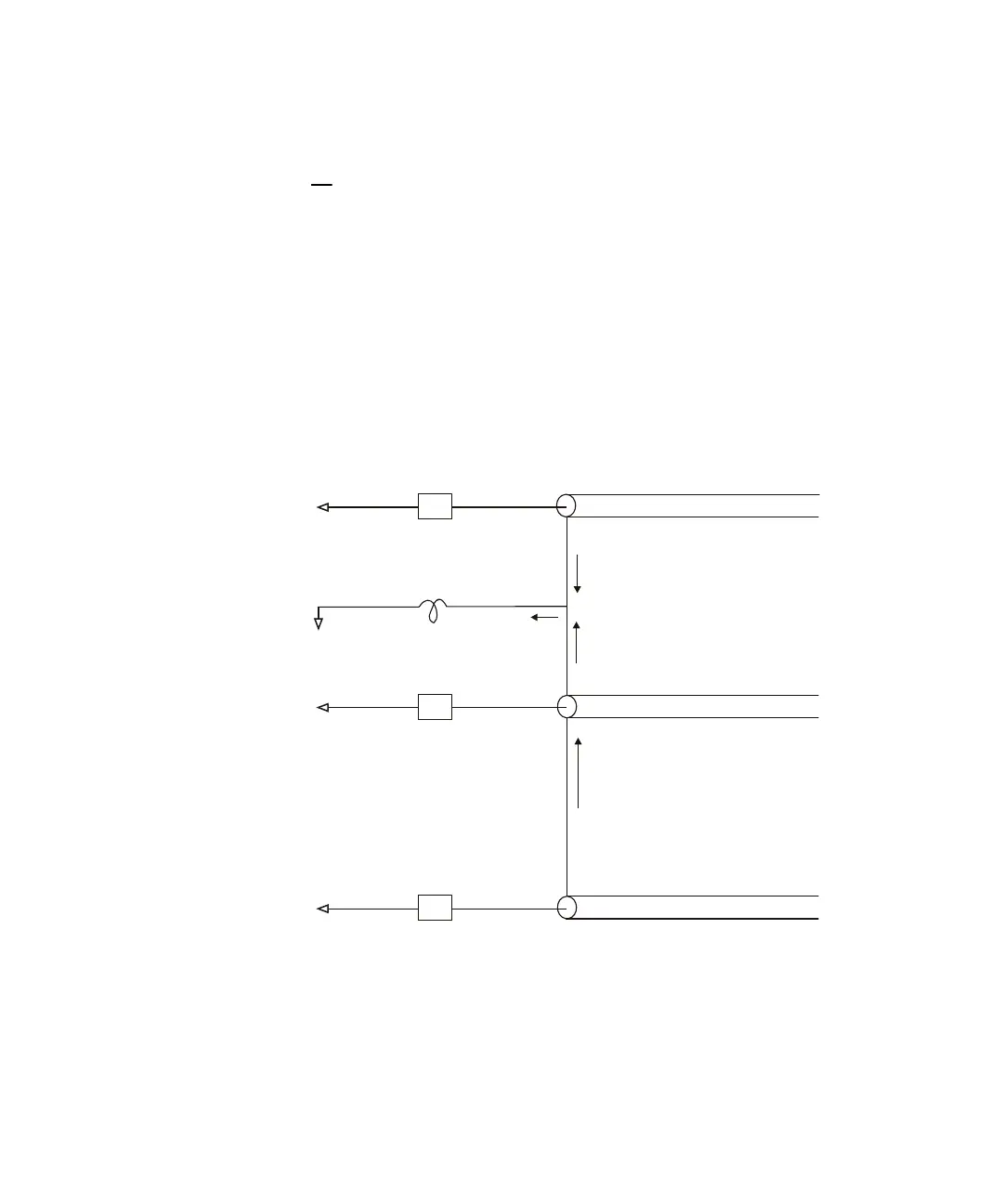
Figure 24 Common Mode Input Voltage Model
Z
in
Z
in
i
n
i
2
+i
2
i
1
i
1
+i
n
+i
n
Z
in
Probe 1
Probe
Ground
Probe 2
Probe N
L (GND)
Vn (Common Mode)

 Loading...