Corrections Tab:
The purpose of these controls is the correction (de-embedding) of different linear
distortions and differential delays added by cabling and fixturing, PCB interconnections,
etc.
The following controls are included:
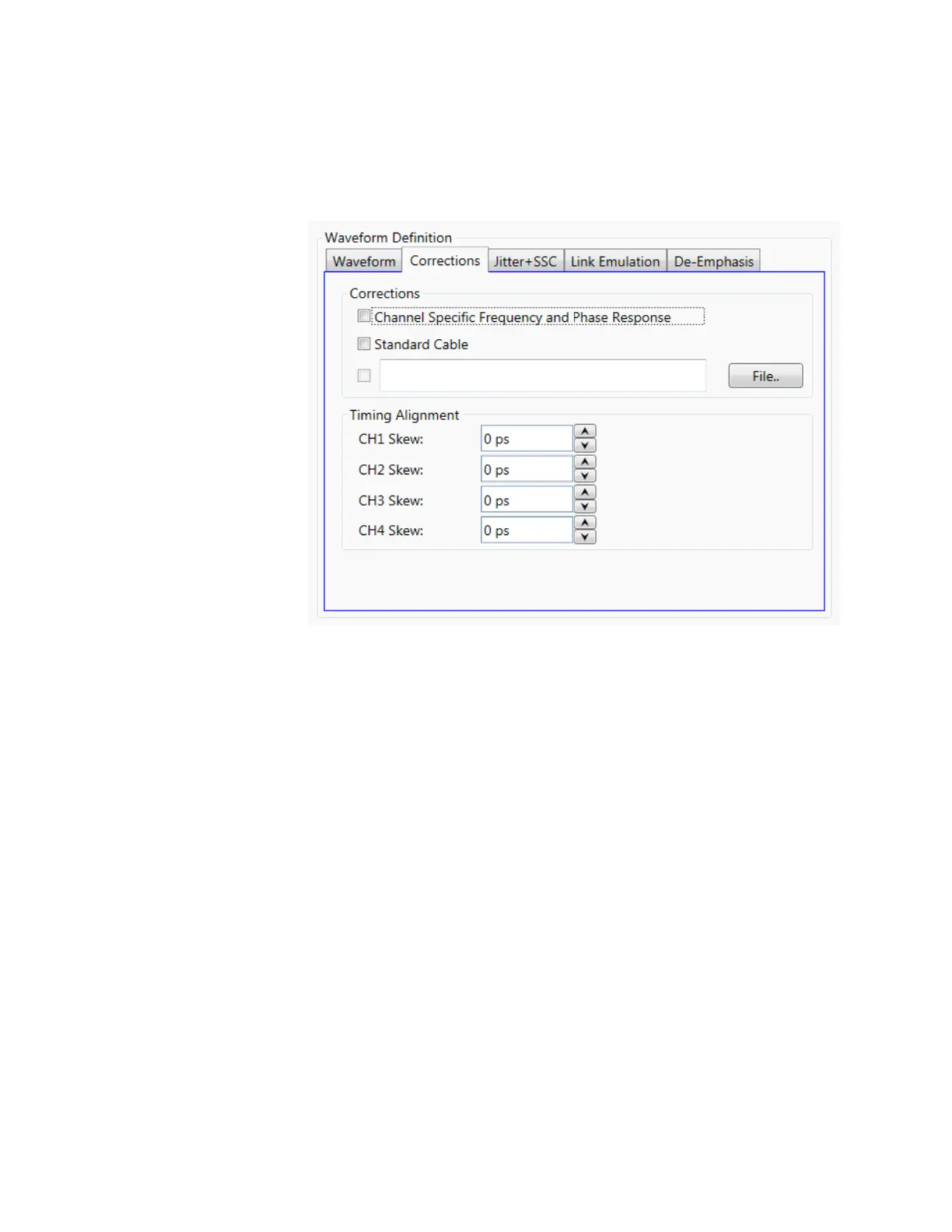
Channel Specific Frequency and Phase Response
This checkbox activates the application of corrections based on frequency-
domain calibration data stored in the target instrument in non-volatile
memory. It improves flatness and linear phase distortions.
Standard Cable
This checkbox activates the application of correction factors based on a typical
high-quality, high-bandwidth 0.85m cable (Huber+Suhner type M8041-
61616).
File…
Opens a correction file selection dialog box. Default file extension is CSV
(Comma-Separated Values). The name of the successfully loaded correction
factors file is shown in the field located at the left of this button. The accepted
format for correction files may be found in the Correction File Format section.
In particular, adaptive equalizer models obtained through the Keysight 89600
VSA software can be imported through this procedure to compensate for
linear distortions added by any intermediate component, PCB trace, or cable.
To obtain this model, apply a NRZ signal with sufficient bandwidth to an 89600
equipped oscilloscope and export the resulting equalizer model. Isolated pulse
characteristics of the waveform must be known by the 89600 software so it is
advisable to calibrate the SUT (System Under Test) using a Raised-Cosine
signal with alpha = 1 to maximize the nominal bandwidth for a given bitrate.
The 89600 software must be set up to analyze a BPSK signal with the same
baud rate and baseband filter characteristics.