2KJ/2KH
1-2-16
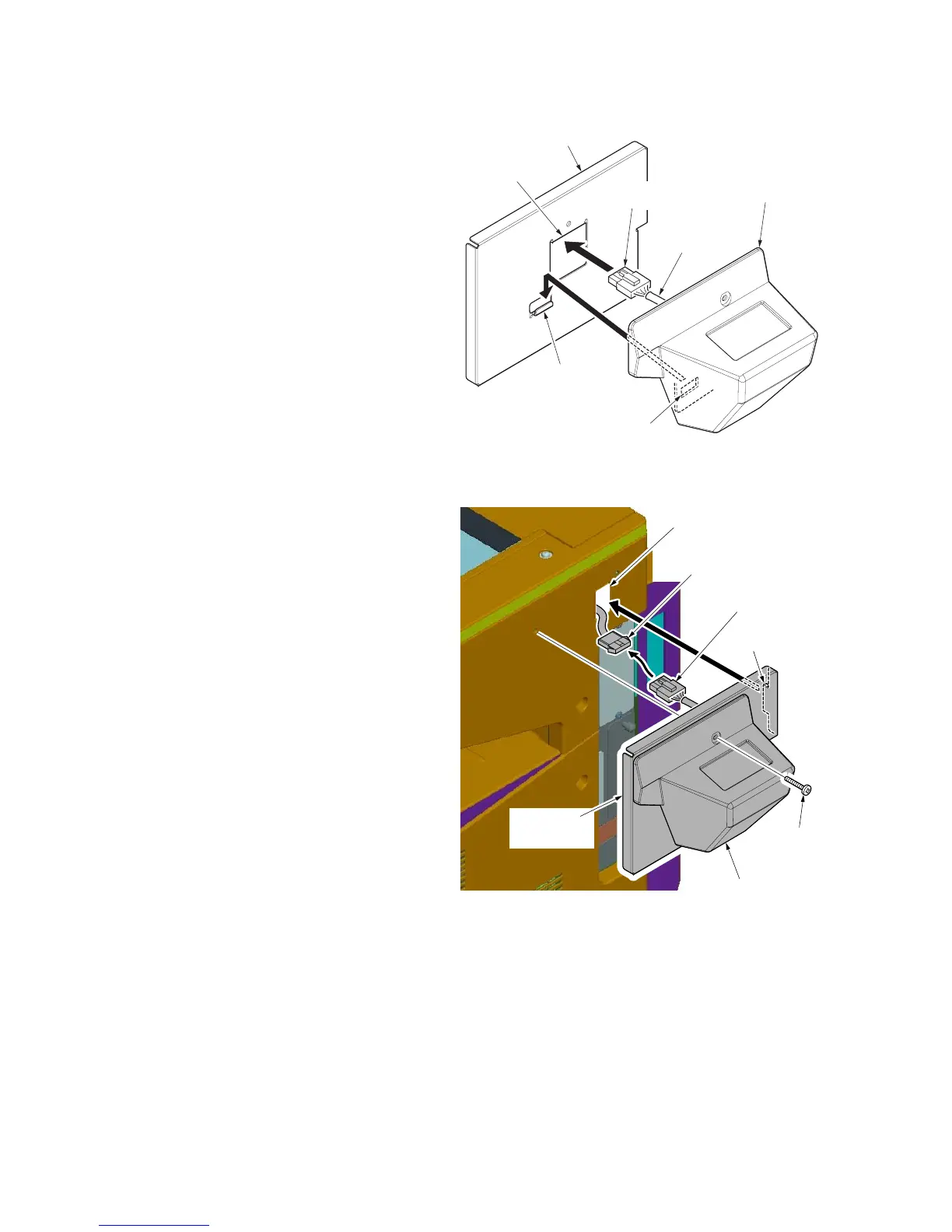
15. Pass the 4-pin connector of the key counter
signal cable through the aperture in the key
counter mounting plate.
16. Hook the square hole on the key counter
cover onto the key counter mounting plate.
Figure 1-2-22
17. Connect the 4-pin connector of the key
counter signal cable to the 4-pin connector
of the key counter wire.
18. Insert the hook of the key counter mounting
plate in the aperture of the right middle
cover.
19. Fit the key counter cover and the key
counter mounting plate using the M4 x 30
screw.
20. Insert the key counter into the key counter
socket assembly.
Figure 1-2-23
21. Turn the main power switch on and enter the
maintenance mode.
22. Run maintenance item U204 and select
"KEY-COUNTER".
23. Exit the maintenance mode.
24. Check that the message requesting the key
counter to be inserted is displayed on the
message display when the key counter is
pulled out.
25. Check that the counter counts up as copies
are made.
Square hole
Key counter mounting plate
(2C960100)
4-pin
connector
Aperture
key counter cover
key counter
signal cable
Hook
Key counter cover
Key counter
mounting plate
M4 x 30
screw
4-pin connector
4-pin connector
Hook
Aperture

 Loading...