GL16 Repair
7-27
26. Turn power ON at the main disconnect
switch and turn the SPEED knob to the
slowest speed.
27. Press the green START button. Run the
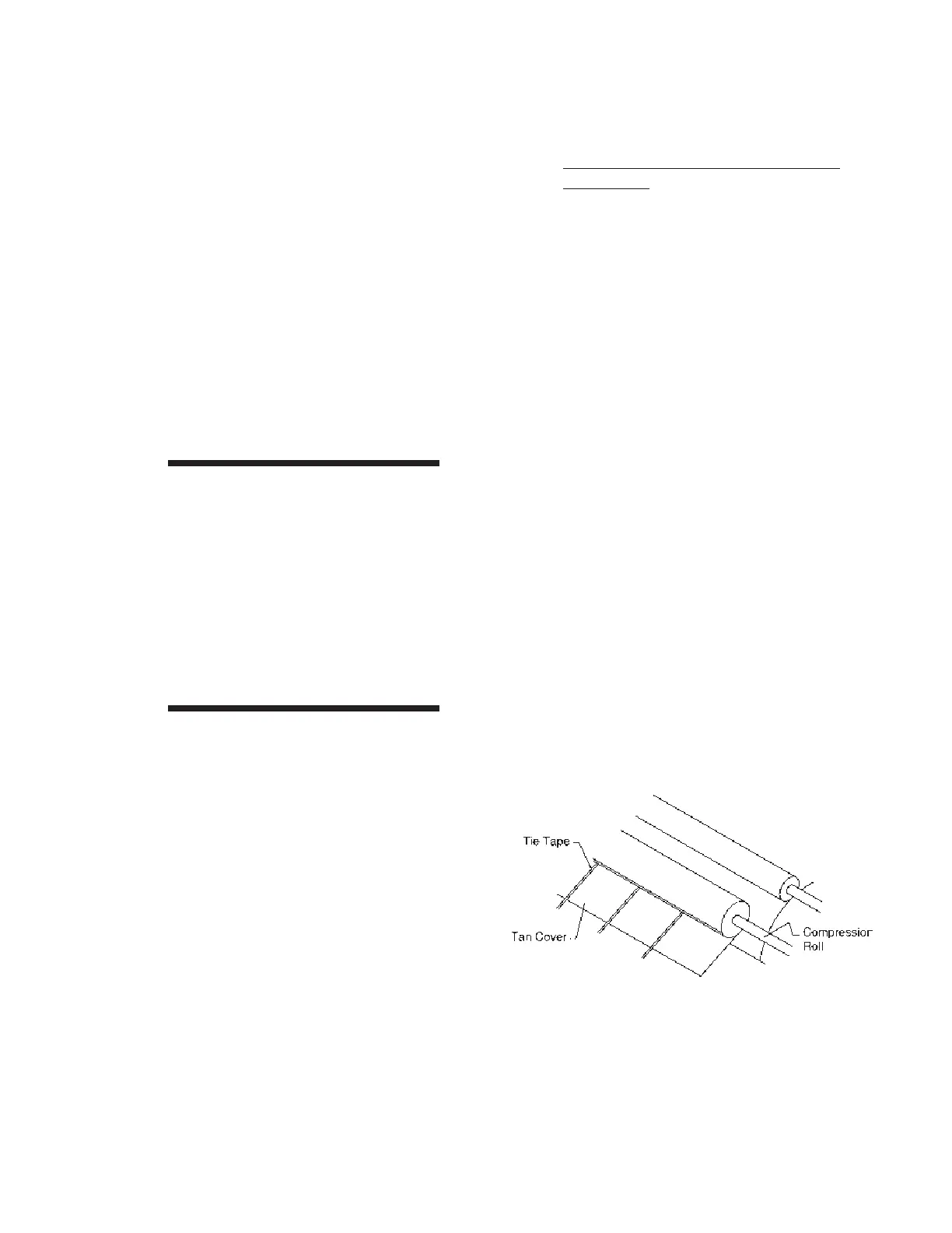
unit until both ends of each tie tape are
positioned at the front of the unit.
28. Press a red STOP button. Turn the power
OFF at the main disconnect switch.
29. Tie the tapes with a square knot. Cut off
any extra length of tape.
30. Tension the compression roll by placing
the spring-loaded handles in their bracket
slots within each end frame.
WARNING
With the safety finger guard
removed, the only means of
stopping the unit is by
pushing a red STOP button.
Ensure that no one attempts
to use the unit until repairs
are completed and all
safety features are
correctly installed.
31. Turn the power ON at the main discon-
nect switch. Start up and heat the unit.
For more information, go back to
OPERATING GUIDELINES chapter,
Operating Controls and Operating
Techniques sections. Run the unit for one
hour with the heat on during the next pro-
cedure. A qualified maintenance person
must remain with the unit at all times until
the safety finger guard has been replaced.
32. While the unit is running, the new pads
and covers will settle in and the pressure
may decrease. Periodically check the
pressure on the compression roll.
33. Press a red STOP button. Turn the power
OFF at the main disconnect switch.
34. Adjust the pressure on the roll. For more
information within this section, go back the
Compression Roll Pressure
Adjustment procedure.
35. Turn the power ON at the main discon-
nect switch.
36. Press the green START button. Repeat
Steps 32 to 35 until the unit has been run-
ning with the heat on for one hour. The
new pad and cover will settle in and the
tie tapes will become loose.
37 Press a red STOP button. Turn the power
OFF at the main disconnect switch.
38. Untie or cut off the tie tapes. Repeat Steps
25 to 27, except let the tapes wrap around
three times.
39. Release the compression roll spring-loaded
handles inside each end frame.
40. Install the red safety finger guard in re-
verse order in Step 6. Make sure that the
lower bolt of the red safety finger guard
rests behind and on the safety switch arm,
inside the left end frame.
Figure 7-27: Tuck one end of each tie tape in the
gap in the tan cover.
 Loading...