360 WM-OM-E Rev I
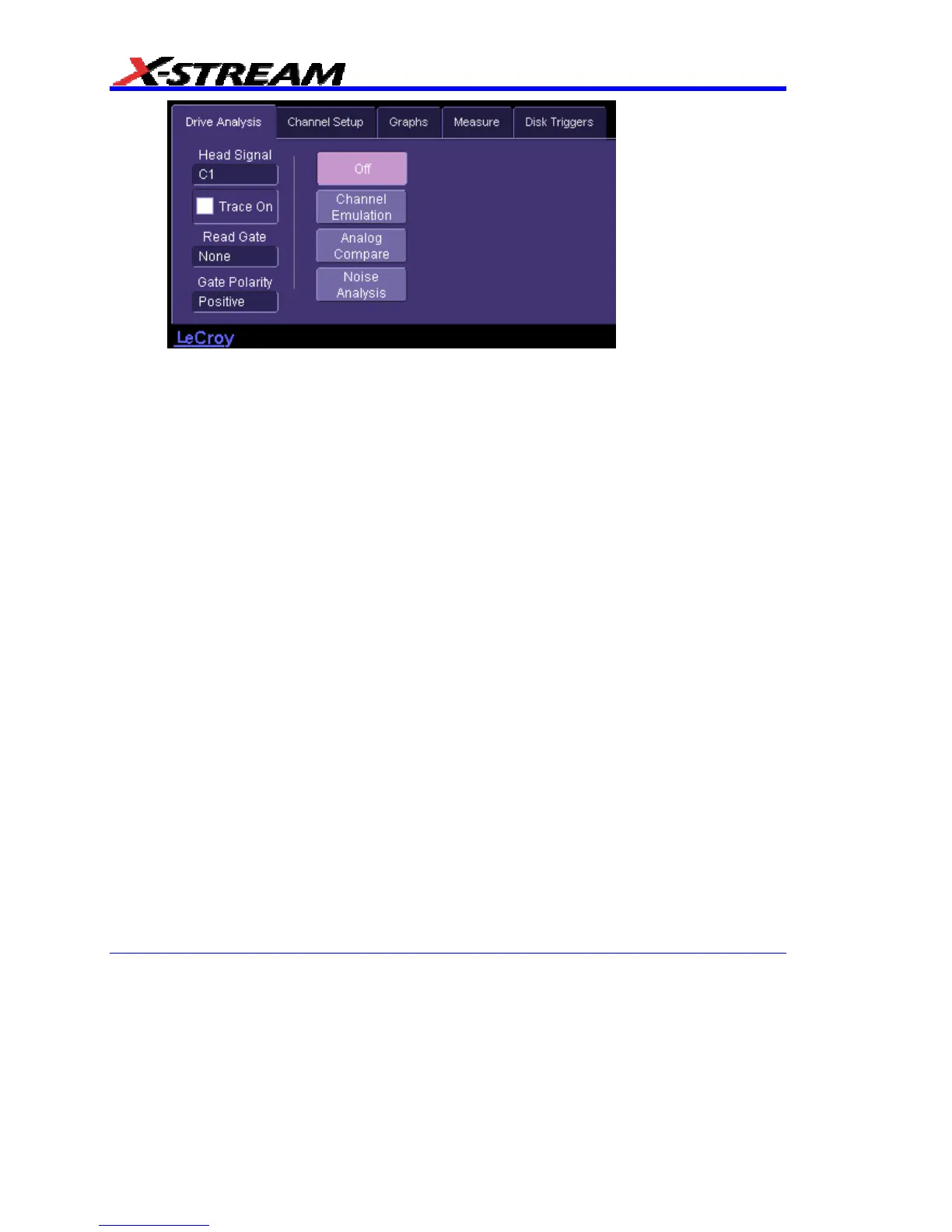
3. Touch the Noise Analysis button. The Noise Analysis setup checkbox, buttons, and data
entry field appear.
4. Touch inside the Head Signal field and select a signal source from the pop-up menu. The
choices comprise channel inputs C1-C4, math traces F1-F8, memories M1-M4, or
Reference.
5. Touch the Trace On checkbox to turn the Head Signal on.
6. Touch inside the Read Gate field and select a source from the pop-up menu. The choices
include Ref and none. Read Gate If the Read Gate signal is connected to a DDA-5005A
channel and specified, it will be used to determine the regions of the signal to be analyzed.
Since the VCO Synch field is required for Noise Analysis with Reference and is normally
present in the head signal in every block just after Read Gate goes true, it is recommended
that Read Gate be used. If Read Gate is not present, the entire waveform will be used
unless the Analyze Region cursors are enabled.
7. If for Read Gate you selected other than none, Touch inside the Gate Polarity field and
select positive or negative polarity.
8. Touch the Setup for Single Frequency button. This action automatically selects
parameters msnr, rsnr, and m_to_r as Source1 in "Measure" dialog positions P1 to P3,
respectively. ParamPassThru is the Measure selection made for each, which means that
the output is the same as the input.
9. Touch the Avg. Samples checkbox to enable averaging.
10. Touch inside the Max Averages data entry field and enter a value from 1 to 32,000 using
the pop-up numeric keypad. Then touch the Reset Average button to clear the previous
average.