h. Record where the cables are connected to the system board assembly; then, disconnect all
the cables.
i. Remove any of the following components that are installed on the system board assembly and
put them in a safe, static-protective place.
•
“Remove the system fan cage” on page 146
• “Remove a memory module” on page 82 (for processor board replacement only)
•
“Remove a heat sink” on page 104
• “Remove a processor” on page 107
• “Remove the CMOS battery” on page 55 (for processor board replacement only)
•
“Remove a riser assembly” on page 89
• “Remove the OCP module” on page 85
j. Pull out the power supply units slightly. Ensure that they are disconnected from the system
board assembly.
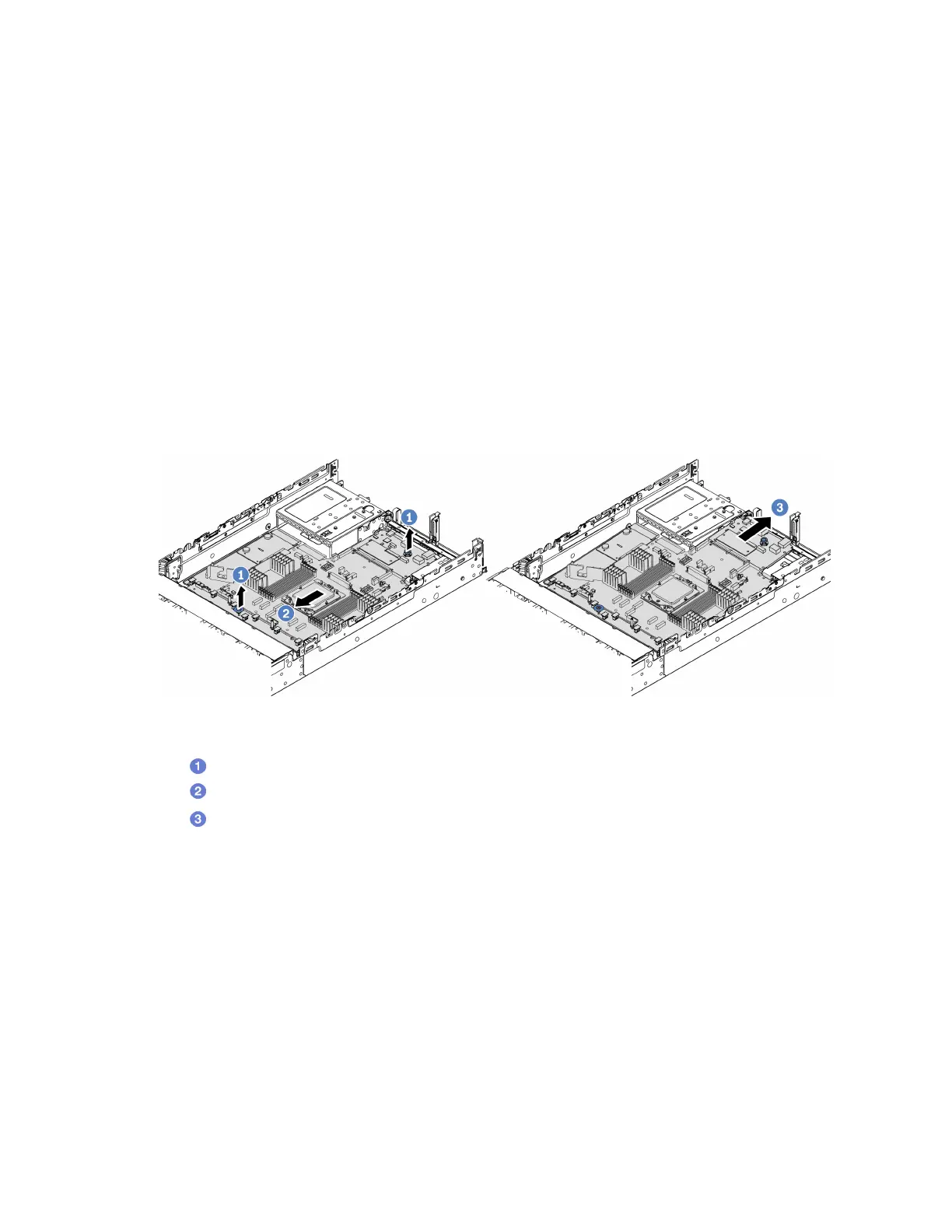
Step 2. Remove the system board assembly.
Figure 101. Removing the system board assembly
a. Lift the two lift handles at the same time.
b.
Slide the system board assembly towards the front of the chassis until it stops.
c.
Tilt and lift the system board assembly out of the chassis.
Step 3. Remove the fan board and the PIB board from the processor board. See
“Remove the fan board”
on page 59
and “Remove the PIB” on page 95.
Step 4. (Optional) If you are going to replace the system I/O board, remove the firmware and RoT security
module from the system I/O board. See
“Remove the firmware and RoT security module” on page
128
. If you are going to replace the processor board, go to the next step directly.
Step 5. (Optional) Remove the MicroSD card. See
“Remove the MicroSD card” on page 79.
Step 6. Separate the system I/O board from the processor board.
Note: To prevent the contact of the system I/O board from damage, pinch and lift the plunger on
the system I/O board upward a little and pull out the system I/O board outward. During the entire
pulling action, ensure that the system I/O board remains as horizontal as possible.
136
ThinkSystem SR655 V3 User Guide

 Loading...


