DLP-513: Detailed Level Procedure 363-206-285
Page 16 of 20 Issue 2, February 2000
DDM-2000 OC-3 MULTIPLEXER
BBG6 STS1E
23. Determine from office records the length of the STS1E cabling between the
DDM-2000 and the STSX cross-connect point.
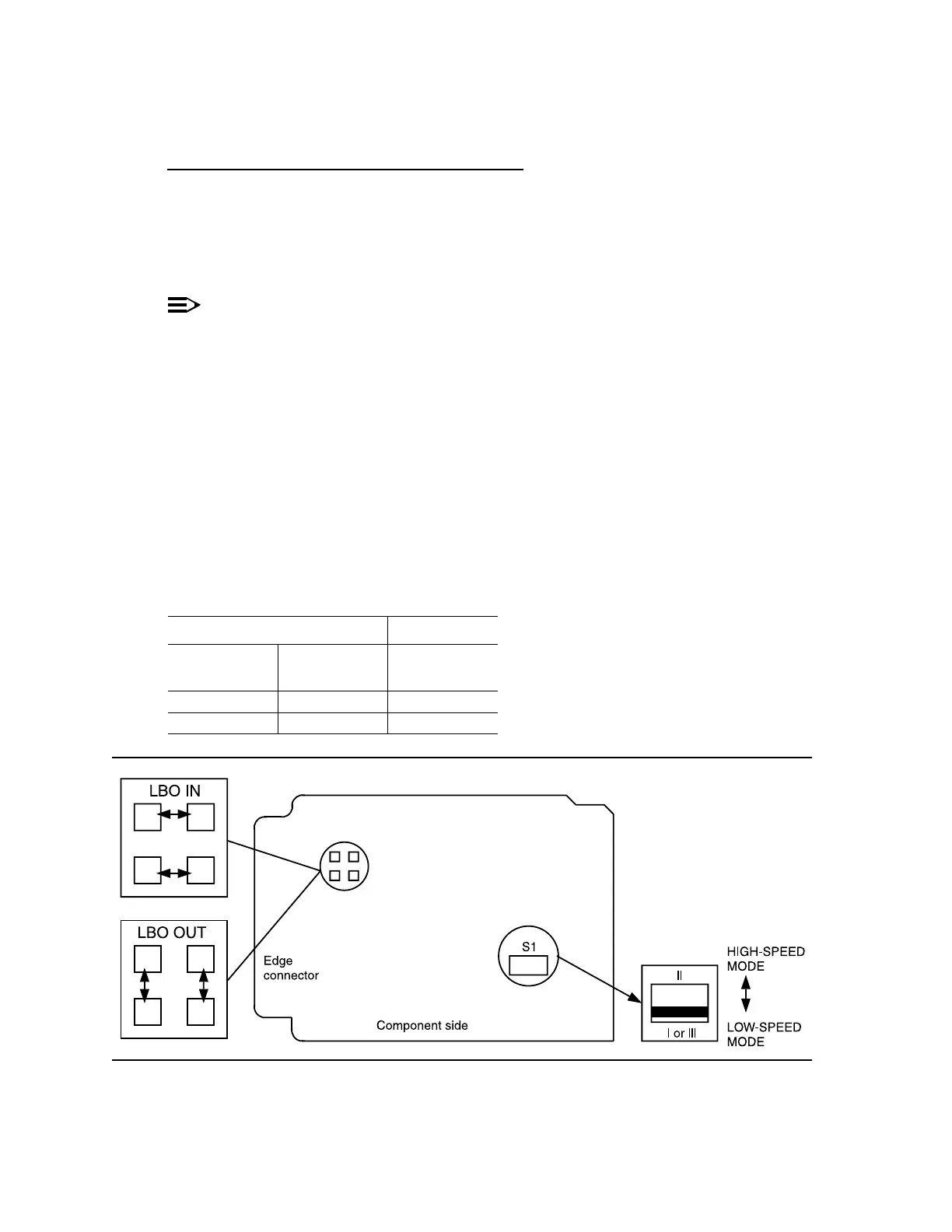
24. Install the STS1E option jumpers per Table L and Figure 7.
25.
NOTE:
The STS1E circuit pack provides bidirectional transport of one EC-1
signal through the DDM-2000 Multiplexer. STS1E high speed mode
interfaces with the DS1/DS1PM circuit packs in a function unit group at
the VT-G rate. STS1E low speed mode interfaces with the OLIU circuit
packs at the STS-1 rate.
Determine STS1E mode of operation (high speed or low speed).
26. Set switch S1 to mode of operation required (HIGH-SPEED MODE or
LOW-SPEED MODE).
27. STOP. YOU HAVE COMPLETED THIS PROCEDURE.
Figure 7 – BBG6 STS1E Line Build-Out Jumpers and Mode Switch
Table L – STS1E LBO Settings
Cable Length (Ft)
734A
Cable
735A
Cable
LBO Setting
0 to 225 0 to 125 LBO IN
>225 to 450 >125 to 250 LBO OUT