363-206-285 Detailed Level Procedure: DLP-523
Issue 2, February 2000 Page 20 of 30
DDM-2000 OC-3 MULTIPLEXER
BBF1/BBF1B DS1/BBF3/BBF3B DS1PM
34. Determine from office records the length of the DS1 cabling between the
DDM-2000 and the DSX-1 cross-connect point.
35.
NOTE:
Switch 1, sections 1 through 3 (S1-1, S1-2, S1-3), are set according to
the length of DS1 cabling between the DDM-2000 and the DSX-1
cross-connection. Switch 1, sections 4 through 7 (S1-4, S1-5, S1-6,
S1-7), are set for the type of line coding (B8ZS or AMI) required of the
DS1 signal. Switch 1, section 8 (S1-8)ontheBBF1/BBF1B DS1 is
unused and ignored by the system. On the BBF3/BBF3B DS1PM, S1-8
must be set to OFF.
NOTE:
To set switch to ON, depress rocker or slide switch toward side labeled
ON in the figure. To set switch to OFF, depress rocker or slide switch
toward side labeled OFF in the figure.
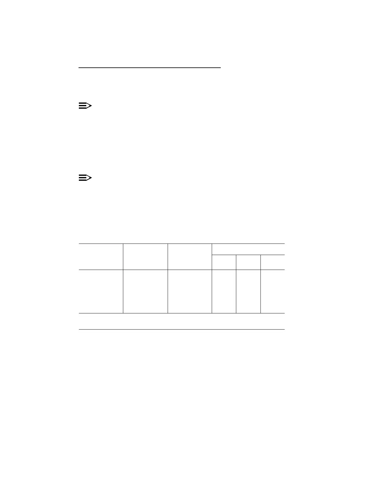
Refer to Table J and Figure 5 and set LBO option switches.
Table J – DS1/DS1PM Cable LBO Settings (Note)
613C (608C)
Cable Length
(feet)
1249C Cable
Length (feet)
Other Cable
dB Loss at
772 kHz
Switch S1 Settings
S1-1 S1-2 S1-3
0to133 0to90 0to0.6 OFF OFF OFF
>133 to 267 >90 to 180 >0.6 to 1.2 OFF OFF ON
>267 to 400 >180 to 270 >1.2 to 1.8 OFF ON OFF
>400 to 533 >270 to 360 >1.8 to 2.4 OFF ON ON
>533 to 655 >360 to 450 >2.4 to 2.8 ON OFF OFF
Note: Invalid switch settings will cause the FAULT LED to light and a
DS1 CP failed alarm.