363-206-285 Detailed Level Procedure: DLP-523
Issue 2, February 2000 Page 26 of 30
DDM-2000 OC-3 MULTIPLEXER
BBF8 HDSL
47. Determine circuit pack option switch settings from office records, work order,
or old circuit pack settings.
48. Set HDSL option switches per Table M and Figure 7.
49.
NOTE:
If a signal has previously been applied to the original HDSL circuit pack,
the FAULT LED may flash when the new HDSL is installed until the signal
tests good.
Remove old HDSL and install replacement HDSL.
Response: FAULT LED on the HDSL flashes for about 15 seconds
and then goes off.
50. STOP. YOU HAVE COMPLETED THIS PROCEDURE.
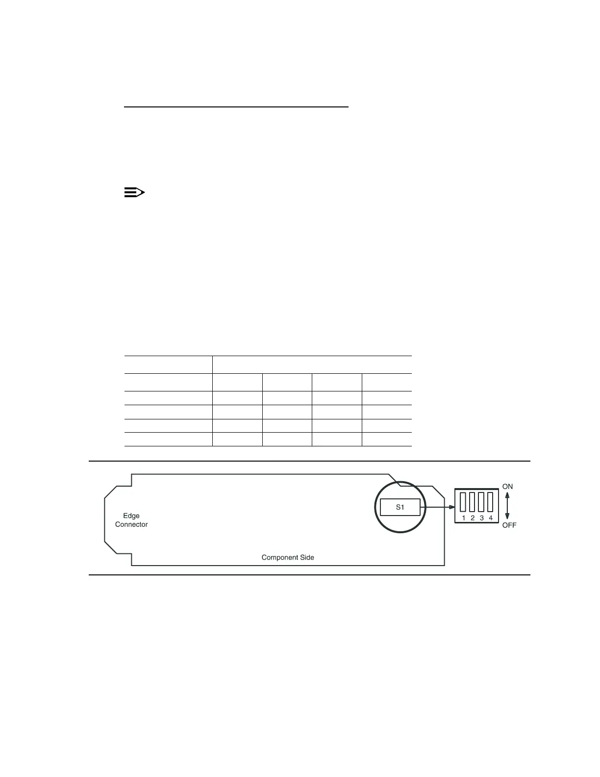
Figure 7 – BBF8 HDSL Control Switch
Table M – HDSL Control Switch Settings
Control Settings Switch S1 Settings
S1-1 S1-2 S1-3 S1-4
Master —OFF—OFF
Slave — ON — ON
Local OFF — OFF —
Remote ON — ON —